Continue to Site

Eng-Tips is the largest engineering community on the Internet

Intelligent Work Forums for Engineering Professionals

  • Congratulations KootK on being selected by the Eng-Tips community for having the most helpful posts in the forums last week. Way to Go!

Floodwall Design - upward water pressure versus buoyancy uplift

Status
Not open for further replies.

Liam Nesson

Structural
Sep 8, 2016
61
Hi All,

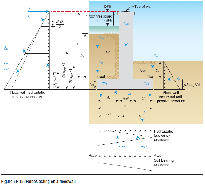
I am designed a cantilever floodwall to FEMA259 for the first time, the process seems relatively straight forward given the layout of the standard and worked examples provided.
Capture1_a8k5un.png


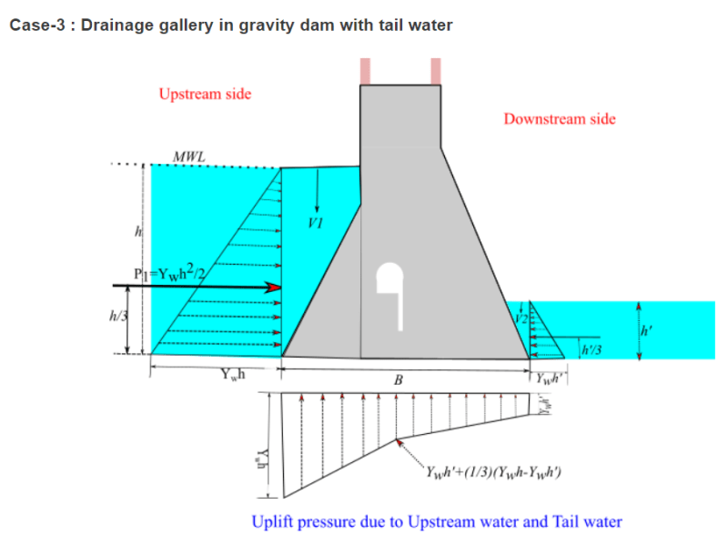
From what I understand, for Dam design the vertical downward and upward forces due to water pressure are considered. V1 and V2 being the downward forces, the base uplift pressure is the density of water times the height of water.
Capture_acu45i.png


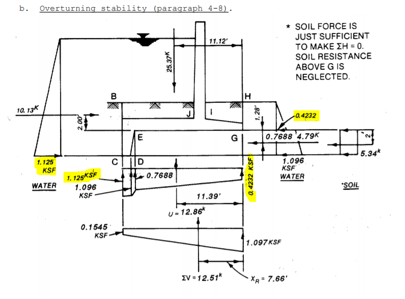
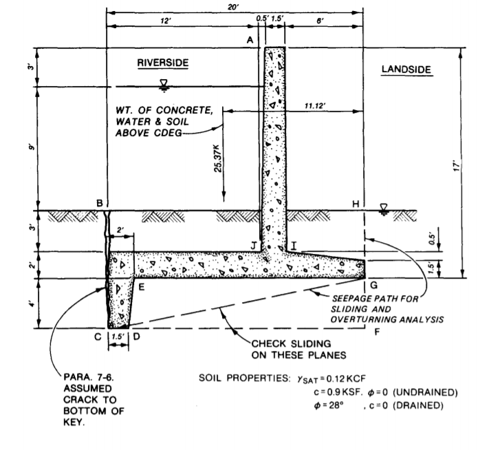
Fema on the other hand use downward vertical pressure combined with buoyancy pressure (not vertical upward pressure). It looks like it is double counting the downward pressure. Buoyancy is the vertical uplift pressure minus the vertical downward pressure on a submerged mass. W,wh and W,st are the downward forces due to water and f,buoy1 and f,buoy2 are the buoyancy forces acting upwards on the base. The formula used for buoyancy is the volume of the wall below the water elevation times the density of water.

Capture2_kabw0j.png


1. I would like to hear other peoples take on this.
2. I am being to loose faith in this standard. They have done some other strange things that I have not seen before, treating the saturated soil on the flood side like a liquid to calculate the lateral pressure. Is that standard practice, I guess its conservative?
 
Replies continue below

Recommended for you

I am not sure if I am answering your question, but I have discovered the following when I analyze a three dimensional concrete structure subjected to buoyant uplift:
* If you include the buoyant uplift pressure as a load (let's call it X), the resulting upward soil pressure will be a certain amount (let's call it Y).
* If you do not include the buoyant uplift pressure as a load, the resulting upward soil pressure will be X + Y.
This is simply stating what should be obvious (but was not to me at first)--statics must be satisfied. The buoyant uplift pressure is helping the upward soil pressure to satisfy vertical and rotational equilibrium.

So...what I do now is I first check the structure for stability against buoyant uplift (the Corps of Engineers allows you to use different safety factors depending on if the load is usual, unusual, or extreme). Then, I design the structure without including the buoyant uplift pressure as a load.

I am curious what others do.


DaveAtkins
 
DaveAtkins,

That method appears to be OK, with one exception.

Neglecting buoyant force causes a more uniform soil resisting pressure, because the eccentricity of all the loads is less.
When you include buoyant force, the overturning moment is resisted by a smaller net weight of structure, so the eccentricity is higher and the resultant resisting soil load moves toward the toe, That increases soil pressure directly below the toe. Depending on the magnitude of the buoyant force and structure weight, that soil load might in fact cause the highest soil pressure under the toe of any design case. It may also cause the greatest moment in the footing below the face of the wall.

If you make the maximum eccentric load soil bearing and concrete moment check at the same time that you are checking safety against overturning, then it appears to be OK.

 
Liam Nesson said:
I am being to loose faith in this standard.
They have done some other strange things that I have not seen before, treating the saturated soil on the flood side like a liquid to calculate the lateral pressure. Is that standard practice, I guess its conservative?

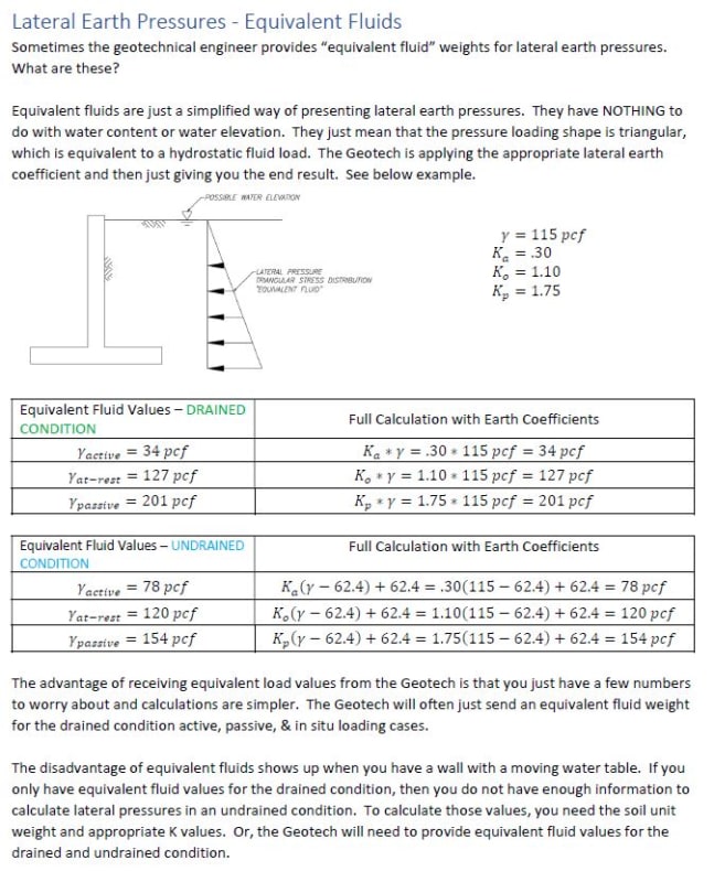
That is called "Equivalent Fluid Pressure" and it was standard practice from early to mid 20[sup]th[/sup] century. It is sometimes used today, but not often (I like it). The method is not necessarily conservative, but can be. It is based on reasonable assumptions and can give acceptable results.

This FEMA publication, without explanation, assumes the Engineer is familiar with and comfortable using, in this case, an outdated way addressing lateral soil pressure. If the remainder of this pub is that way on other calcs, IMHO, you are wise to question the document's usefulness.

[idea]
 
Maybe I am behind the times, but we use equivalent fluids almost exclusively to design retaining walls and other embedded structures. (In Houston; our soil stratums are usually just clay 1, clay 2, clay 3, etc.. all with similar properties; so we do not worry about radical changes in soil properties on our walls)

I made the following notes for myself and to explain to EIT's....
Capture_kdj3dy.jpg


**EDIT.....in my examples above, I am using Rankine pressure. The geotechs could be using Coulomb; or other methods to arrive at their equivalent fluid number.
 
Fair enough, I'll edit my recommendation to the OP.

Liam - That is called "Equivalent Fluid Pressure" (EFP). The method is not necessarily conservative, but can be. It is based on reasonable assumptions and can give acceptable results.

This FEMA publication, without explanation of EFP, assumes the Engineer is familiar with and comfortable using it to address lateral soil pressure.

If the remainder of this pub is that way (equations with no explanations) on other calcs, IMHO, you are wise to question the document's usefulness.

[idea]
 
USACE EM 1110-2-2502 (1989) is still the go-to standard for flood walls, and it is what I use for any wall that has buoyancy and pore water pressure above the base.
If you haven't seen this document, give yourself some time. Not a quick read.
It appears that FEMA is just providing a simplified approach by combining / smearing load diagrams (?).
My load diagrams always separate out the water pressures from the soil pressures. More triangles and trapezoids, but easier to define actions.
When you reference vertical soil "bearing" pressures, it is helpful to define net vs gross, particularly when buoyancy is involved. In the solution process, you first solve for net pressures, with buoyancy being a driving moment. The total vertical soil pressure is q_total = q_net + buoyancy. This is what you use for structural design.
 
Hi All,

Thanks for the responses, I appreciate it.

The USACE EM 1110-2-2502 looks like a great reference, I know what I will be reading now in my spare time. Already it has answered my question regarding uplift, the FEMA document appears to be incorrect.

Capture_anuejv.png


As for the equivalent fluid pressure, it appears to increase the active pressure of the soil and reduce the passive resistance. Again some more reading to do.
 
Status
Not open for further replies.

Part and Inventory Search

Sponsor