Continue to Site

Eng-Tips is the largest engineering community on the Internet

Intelligent Work Forums for Engineering Professionals

  • Congratulations KootK on being selected by the Eng-Tips community for having the most helpful posts in the forums last week. Way to Go!

ACI 318 Coupling Beams: When is a beam a beam

Status
Not open for further replies.

Gumpmaster

Structural
Jan 19, 2006
397
I have a special concrete shear wall building with coupling beams (ACI 318-14). It's a 3 story low rise building made entirely out of shear walls. The gravity system is thick slabs (14") with stout beams and columns. My question is about when is a coupling beam a coupling beam. I have many instances of two stacked openings but in all cases, the l/h is less than two and my Vu is less than the limit for diagonal reinforcing. I have a ton of beams that are 8ft long and 12ft tall. It doesn't appear that ACI 318 provides any outs from considering a horizontal wall segment (See ACI 318-14 fig 18.10.4.5) as a coupling beam. So, when is a horizontal wall segment realistically no longer a coupling beam? The difficulty with considering everything a coupling beam comes when you have to detail those beams per 18.6.3 through 18.6.5. Having hoops on a 12ft deep coupling beam is difficult.

I have several instances of a man door at the bottom of the wall with nothing above it. My l/h is 3.33ft/53ft. ACI 318 would apparently consider that a coupling beam, but that doesn't make a lot of sense.
What about a 12ft tall x 8ft wide beam? That seems closer, but your design shears (Mpr/L) can get very, very big.

I would normally apply some engineering judgement in this case, but many building departments don't allow engineers to have judgement. I think, in general, these provisions are there with higher rise buildings in mind that derive most of their lateral resistance from a compact shear wall core, not an expansive low rise building with 600 feet of shear wall in one direction.

FYI, for ease of analysis, I'm looking at this in RAM Structural System which makes it difficult to simply ignore the coupling beams and not count on their contribution.

What are your views on this subject?

Thanks.
 
Replies continue below

Recommended for you

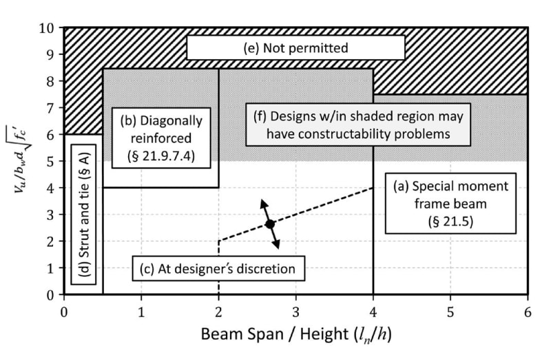
The following fig. explains the coupling beam design space. Excerpt from Seismic Design of Cast-in-Place
Concrete Special Structural Walls and Coupling Beams. (NEHRP Seismic Design Technical Brief No. 6)

If you post the structural plan and coupling beam details , you may get more helpful responds..


Coupling_beam_design_space_ggfkxy.jpg
 
I'm hoping to not call them coupling beams at all. Surely there must be some point at which a section of wall above an opening isn't considered a beam. Per the chart above, which I'm familiar with, I would need to do the strut and tie method for my 3'-4" wide, 53' tall "beam" above a man door. That's just not happening. This is more of a fundamental question than about specific detailing. That said, for those of you who have had 12 foot tall coupling beams, how did you provide hoop ties? It would seem you couldn't do that without having a lap splice in the hoops which I don't think is the intent.
 

In this case, can be called perforated wall . You may perform analysis with a strength reduction depending on opening percentage. Or modelling with finite element always an option.

I will suggest you to look NIST GCR 14-917-25 and you may reach from the following link ..

 
Thank you for that NIST report reference. It was interesting. I think calling this a perforated wall would be what I would want to do, but I didn't see any recommendations for perforated walls in that report. I don't think the word "perforated" shows up in the report at all. Appendix D of the report appears to indicate that shear failure of the piers between spandrels may be important. The report does address stacked openings quite a bit, but mostly concentrates on the wall region directly below stacked openings which is an interesting area of increased stress that ACI 318 doesn't appear to address.

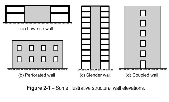
Are there any references for the design of perforated concrete shear walls? NIST GCR 11-917-11 provides the below figure that appears to show a perforated wall is different than a coupled wall, but it doesn't provide any reason one wall would be considered perforated an another would be coupled. Are there any criteria for determining if a wall is perforated vs coupled?

Perforated_Wall_ierwez.jpg
 
Unfortunately I don't know of any geometric limits that define whether or not a beam should be treated as a coupling beam, but in your case I think it's more meaningful to approach this in terms of demand. With 600 ft of shear wall in one direction, I imagine that you don't require much ductility out of the walls. You might try some of the strategies below to assess whether special detailing is required.

• Model the coupling beams and impose the rotation seen at maximum drift (δ = C[sub]d[/sub] δ[sub]e[/sub], δ = R δ[sub]e[/sub], δ[sub]MCE[/sub] = 1.5 R δ[sub]e[/sub], etc.). You may find that the demand is low enough that the coupling beam behaves elastically.
• Assess the coupling beams according to ASCE 41 as conventional RC coupling beams with nonconforming transverse reinforcement.
• Design the coupling beams to remain elastic (V[sub]u[/sub] = Ω[sub]0[/sub] V[sub]e[/sub], V[sub]u[/sub] = R V[sub]e[/sub], etc.). See Paulay and Priestley Chapter 8 on buildings with restricted ductility.
• Design the coupling beams to remain elastic for the forces induced by a mechanism in the wall piers. Understand that this might promote a story mechanism during an earthquake. See Paulay and Priestley sections 5.2.3(b) and 7.2.1(b).

At a bare minimum I would provide u-bars at the head and sill to be lapped with the vertical wall reinforcement. As you alluded to, you may have to make your case to the AHJ if you decide to omit the detailing.
 
Some fun posts on eng tips related to this... unfortunately I've come to the conclusion that this in the abyss of "engineering judgement" whether to assume "fully coupled walls" vs "individual wall piers"


[URL unfurl="true"]https://www.eng-tips.com/viewthread.cfm?qid=479013[/url]
[URL unfurl="true"]https://www.eng-tips.com/viewthread.cfm?qid=478388[/url]

The first link posted shows how treating an example wall stack as "fully coupled" (not sure if that is the correct term) has about ~1.65 (0.8/0.52) more flexural capacity than treating the wall as individual wall piers.

To determine whether the walls are fully coupled though is really up to engineering judgement from the research I have seen.


S&T
 
Thank you Decker and sticksandtriangles for both your responses.

Decker, I very much like your suggestion to design the coupling beams to remain elastic. In one of my particular "beams" Vu = Ω0 = 270 kips while Mpr/L =1600 kips. It's a significant difference. I'm not sure that the AHJ will buy it, but I can hope. It's interesting that AISC 341, in general, includes the provision that you should design many things for Mpr or the plastic tension, but the force need not exceed the amplified seismic load while ACI 318 has no similar provisions. It would be common sense, to me at least, that you should be pretty safe if you design sensitive elements for elastic level loads. I think you could also effectively argue that, if you design for elastic loads, you'd need fairly minimal detailing because you mostly eliminate the need for ductility. Thank you also for the reference to Paulay and Priestley; I didn't have that one.

sticksandtriangles, I looked at all the past conversations about this that I could find but, like you, I didn't find anything that's very conclusive.

This is definitely a point where ACI 318 can improve. Does anybody know someone on the ACI 318 chapter 18 committee that could argue for the elastic design approach?
 
One caution I'd point out about using Ω[sub]0[/sub] is that it is predicated on developing some yielding / inelasticity at code level forces in order to cap the demand on the coupling beam. Since you have 600 ft of shear wall I'm guessing you have a lot of inherent overstrength in the walls and you won't be anywhere close to yielding at code level forces. If I were reviewing the design, I'd be more likely to buy off on it if you used R as your overstrength factor rather than Ω[sub]0[/sub].

In my opinion the ASCE 41 method is the most likely to gain AHJ approval (if the reviewer even flags the issue) just because it is codified. It also includes provisions to account for limited ductility in beams with nonconforming stirrups. That said, I know it's probably more work than you'd like to take on.
 
Status
Not open for further replies.

Part and Inventory Search

Sponsor