Continue to Site

Eng-Tips is the largest engineering community on the Internet

Intelligent Work Forums for Engineering Professionals

  • Congratulations IDS on being selected by the Eng-Tips community for having the most helpful posts in the forums last week. Way to Go!

Composite beam (H beam encased in concrete) connection to top of concrete buttress? 1

Status
Not open for further replies.

Redacted

Structural
Mar 12, 2016
160
Hi there, I've been tasked to design a solution to fix this problem (see attached images)

The problem:
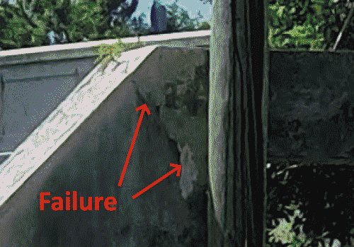
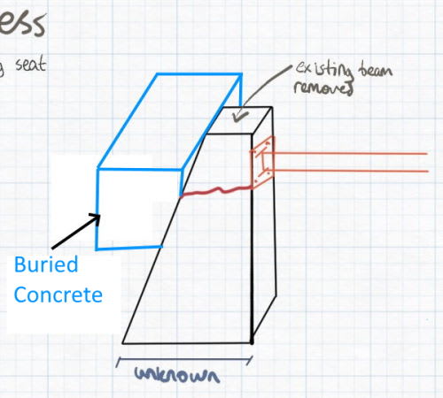
1. Existing concrete beam-column on top of the buttresses has experienced corrosion of the inner steel member that has expanded and caused delamination of the concrete, which is now falling onto the motorway beneath it (The existing has lasted about 50 years).

The road is closed until this issue gets resolved.

2. Historical drawings of the road are not available and they are expecting a quick solution. Therefore conservative assumptions need to be used.

The solution:
I thought about potentially saving the beam by using some bolted channel sections but not sure if those would be adequate in compression and the quality of the beam concrete seems poor, so I will just replace them, which the client is happy to do.

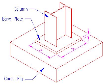
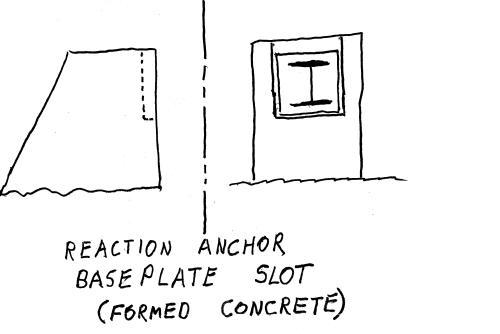
I am thinking of using a concrete-encased steel H beam. I am assuming the buttresses are in adequate condition and plan to use those for the new beam. I am planning to replace the beam with one of the same cross-section dimensions so that the overall weight of the beam is not higher than the original.

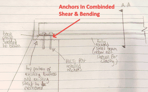
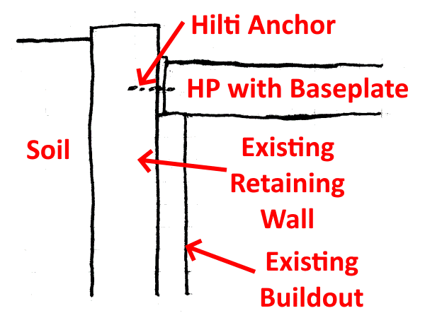
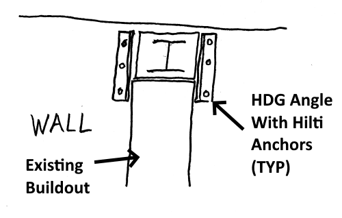
I am wondering how I can connect this new beam to the buttresses so that the connection can effectively take the axial compression loads etc. Essentially I would like to know what the most efficient connection detail to transfer the force from the beam to the buttress is.

I'm roughly thinking of some type of system using post-installed anchors in the buttresses, bolted to the beam flange and concreted over?

I'm not sure if there is a common connection detail for something like this or not. If anyone can provide assistance or point me in the direction of helpful advice applicable to this design, that would be greatly appreciated.

Beam-column has a clear span of about 16', with a depth of 1'8" and width of 2'.

It's a strange structure as the steel inside the beam-column appears to be an old train track?

I am also assuming that these beam-columns are acting as lateral bracing for the adjacent retaining walls.
 
 https://files.engineering.com/getfile.aspx?folder=b43ab0c1-176f-481d-bf00-d96a9bc8e8f2&file=engtips_beamcolumn.pdf
Replies continue below

Recommended for you

The "beam" appears to actually be a strut (horizontal column) that resists loading for soil pressure behind the buttressed retaining wall. The necessary reaction anchor is on the other side of the motorway. The only significant loading is compression. In addition to the strut the reaction anchor looks to be failing:

Reaction_Anchor-500_i8vf86.png


I see two ways to approach this project:

1) Get a good geotech involved to see if some type soil anchors can be installed to restrain the wall and delete the strut.

2) Make structural repairs to the strut/anchorage/wall.

For structural repair I would consider the following steps (not necessarily in this order)

A) At calculated locations, install temporary strut(s) lower than the existing one.

B) Replace the upper portion of the reaction anchorage.

C) Prepare the wall to accept an new steel strut. I agree with you that an HP is a good shape for the strut. A heavy wall pipe would be good, too.

D) Have thick, oversized baseplates fabricated to both ends of the HP. Have the HP / baseplate assembly hot-dip galvanized and omit the concrete cover used on the previous strut.

E) How to anchor the HP/baseplate to the wall and reaction anchor will have depend on existing concrete condition.
 
Thanks SlideRuleEra, your comments are very helpful so far.

Option 1 won't work in this location, so let's discuss Option 2.

A) I agree, I think that would be a good idea.

B) I agree, I plan to pretty much remove the entire existing beam and the top portion of the reaction anchorage (buttress) that is cracked.

C) Would you mind clarifying what you mean by preparing the wall?

D)I agree with the galvanizing and I think using a simple steel beam would be the simplest and most cost-effective approach (especially as no formwork is required). However, the site location is in a very humid and corrosive environment that tends to corrode steel quickly(even galvanized). Due to this, I was considering doing a fully encased steel beam in RC concrete (see my sketch) mainly from a durability standpoint. I'll probably propose both to the client and let them decide what they want to go with after I explain the durability differences.

E) See my sketch of the detail I am thinking of. Would you mind giving your advice on this? The compression force in the beams seems to be somewhat small ~150kN; I was going to design the connection anchors to be able to resist that in shear. Are there any other significant design effects that I should be considering for the connection?

If the buttresses perform as normal there really shouldn't be much compression going into these struts as they shouldn't be bending but I am assuming the worst case (buttress fails).

The detail in my sketch may work ok for good concrete but I am unsure what sort of connection should be used if the existing concrete is bad when the strut is removed. Any help would be appreciated.
 
 https://files.engineering.com/getfile.aspx?folder=ca229342-d06e-43f3-a8b3-8daba0ce7645&file=20210827_204752_-_Copy.jpg
I'm not convinced that steel with a RC protective layer is cheaper than just straight RC. I mean, the way you have drawn the encasement I gaurentee you the GC will be hiring a proper forming contractor. So...no matter what a forming guy is coming to site. You are paying for a pump. You are paying for concrete. You are paying for designed falsework. Why not just make it a reinforced concrete beam?

That aside, if you go steel I'd be careful about introducing bending into those bolts (not saying you are, but improper detailing could lead to inadvertent bending and not just shear). In addition, breakout of parent concrete would be a real concern for me since the embedment location likely has no ties or similar.

Lastly, as someone who repairs concrete structures for a living...if parent concrete is unacceptable, you keep going. You cannot rely on a connection to parent material of dubious integrity. That's really the only solution if you intend to keep the structure more or less as it was. Chip out to good material, have someone knowledgeable review your concrete repair detail, and pour back prior to adding your beam. If you want to / can completely change the structure then we can discuss cool options to by-pass the repair of parent concrete. Sometimes that's the better way, most of the time it is not.

 
Hi Enable, thanks so much for your comments. I appreciate you providing your expertise!

That’s true, the price may end up being similar. I guess the reason I didn’t go with pure RC is that I wasn’t too confident with how the connection would work (which is my main concern for this project in general – transferring the compression/shear load into an assumed mass concrete buttress).

Does the detail in the attached sketch seem reasonable?

As for the design effects in the steel bolts, yes parent concrete break out will most likely govern (that’s one of the checks I would do with regard to the shear – the hilti tables take that into consideration and gives the respective shear capacity of the bolts). The edge distances may be a bit of an issue that I will need to check. Frustratingly enough, there are no historical drawings for any of this structure, so I need to assume that the buttresses are mass concrete.

Would you mind explaining a bit more about the correct detailing for anchor bending? I would have thought that you would only get bending if there was a gap between the baseplate and concrete layer?

Thanks for the tip regarding bad concrete, I will use that going forward in my career. When deciding on whether the parent concrete is ‘acceptable’, am I mainly checking for obvious issues like cracking, spalling, honey combing and delamination and keep chipping away until it is solid with no visible issues or is there another check that should be done? For the calculations I’ll assume the worst grade of concrete 2500 psi (17.2MPa).

As for the concrete repair detail, I have done a search for some good literature on the topic but I am having a hard time. I would have thought that for the joint between the old concrete and new concrete, would be a bonding agent and either the anchors in the first sketch or post installed rebar in the second would act as dowels tying the two layers together.

Any assistance or sketches you can provide for optimal connection arrangements would be helpful.
 
 https://files.engineering.com/getfile.aspx?folder=a55501d7-e8a8-4842-86cb-3a9283395d21&file=engtuips_conc_beam_detail.jpg
Redacted - I disagree with your fundamental approach to this project. Since original plans are not available, the next best option is to carefully study what I call "the full-size, three-dimensional model", that is the existing structure itself. What I see in the photos is a strut designed/constructed for one purpose - axial compression loading. Perhaps there is additional info that I don't have to disprove this observation.

You are starting with a beam bearing connection and trying to convert for axial compression loading. The only axial loading resistance is provided by the Hilti anchors, which are being sized for a (poorly defined) shear of 150 kN load. And shear is introducing bending into the Hilti anchors by having the HP located above both concrete cover and a baseplate.

Redacted_-_Proposed_Detail-500_csh3fy.png


Also, I continue to disagree with using a concrete-encased HP. You have discounted hot-dip galvanizing, but when correctly specified (required zinc coating thickness) useful life is lengthy, even for humid, corrosive conditions (such as the coal-fired electric generating stations, located on the hot/humid South Carolina coastal plain, where I worked)

Galvanized_Steel_-Time-to-First-Maintenance-Chart-500_suynve.png


An HP that is not concrete encased will be significantly lighter than the same member with concrete encasement. Lighter mean less bending due to self-weight - a good feature for a compression strut. Connections can be much simplified, too.

I have some specific thoughts on a conceptual compression strut design, and will be happy to discuss... but only if you are willing to get past the modified beam bearing and concrete encasement approach.

Regardless what you or I "think", there is one step that will answer many questions:

You say the motorway is closed.
Install the temporary strut(s).
Remove the existing strut and how it the structure was designed/built, and evaluate the work area.
 
@SlideRuleEra

We are on the same page with your observation. In the OP I mentioned that the strut is acting as a beam-column element (as in subject to bending from self-weight and axial compression from the adjacent retaining walls).

Yes, the bearing connection is perhaps not the most efficient, which is the reason for starting the thread. I thought that the bearing connection would be the simplest approach. I was planning to size the anchors so that two out of the four can take the full shear force. I note your point about the bending; the appropriate HILTI reduction factors could be used. This is the only connection I was familiar with in this scenario so your expertise on a better solution would be greatly appreciated.

I also note your point about the HP section and I don't disagree. I feel that there are many benefits (weight, cost, ease of installation, speed of installation etc). The main reason I was considering an encased steel beam is because that it is what the client said they would prefer to use in the initial site visit.

As a result, I would like to propose two concepts - steel only and fully encased, highlighting the advantages and disadvantages of each (unless the encased or concrete beam is completely impractical). Although to do this I will need the concepts firmed out. They are looking for concepts by Tuesday, which is why I am scrambling currently to iron these out.

I would love to hear your thoughts on the concepts for this - I am open to better ideas.

I agree that step will answer a lot of questions. However, the client is looking for a concept first so that they can start to create a budget for the work. The details can be revised after the demo is done and the existing structural condition inspected.
 
Can you use an HSS section in lieu of a rolled one? There are zinc-rich epoxy coating systems that are much better than HDG. For expediency, I'd avoid a reinforced concrete solution.

Rather than think climate change and the corona virus as science, think of it as the wrath of God. Feel any better?

-Dik
 
Redacted - Because of your time constraint, I'll post the "bottom line", without explanation. Look it over, think about, post to let me know you have seen it, and we can discuss it tomorrow.

Note: Although what I am proposing is based on speculation & assumptions about how the existing project was designed/constructed, it may be a reasonable solution that has many advantages:

Take this:
Column_Baseplate_jaojot.jpg


Then, rotate all of it 90 degrees (including the "Column Ftg." which now represents the "Existing Retaining Wall")
Redacted_-_Proposed_Compression_Strut-600_wh1ebp.png


We can get into why tomorrow.
 
@Dik Thanks, an HSS solution would have a lead time as there is only one steel supplier here and they don't have stock HSS. I agree, there are some zinc-rich systems that will match or surpass a HDG coating. Noted about the concrete solution.

@SlideEraRule Thank you very much for this, I do see quite a few benefits with your detail :

- axial force is acting centrally and therefore there are no significant additional eccentric moments added into the system as a result
- edge distances for the concrete break out are larger
- shear force in the bolts is lower as it is just the beams self-weight (if the bearing surface fails).

If there are other benefits I would be happy to discuss to learn of them as well.

I agree this would be the better option.

A few questions though :

1) One of the benefits of the original detail is that it was easy to replace the beams if they did end up corroding over time. The nuts could have been removed and the beam lifted out and replaced. With your detail is there a way that it can be detailed to allow for future replacement, without cutting/destroying the anchors?

2) The way your sketch is shown, the beam flange is bearing on the 'build out', and also has the Hilti anchors. Just so that I understand, the Hilti anchors are mainly there in the event the 'build out' fails to hold the beam up by means of shear, and for general fixing during construction?


Is a precast concrete strut an option you would have available where you are? That would get you out of needing formwork, avoids the potential for steel corrosion, and precast concrete is typically higher strength and less permeable than CIP concrete. Typical concrete cover for precast is less than for CIP, but that is easily adjusted if greater cover is called for. If you have a precaster in your area, the delivery timeframe may be similar or less than for steel.

Rod Smith, P.E., The artist formerly known as HotRod10
 
@BridgeSmith

Unfortunately, there are no precast companies here. The closest would be the contractor casting it near the site (not the same quality as a proper precaster doing it) and transporting it/lifting it in place.
 
Redacted - I'll see if can answer your questions:

Other Benefits: You got most of them, but there are some that are more subtle:

Simplified design/construction. I have found, in general, that the higher the loading the KISS Principle becomes more important.​

The strut can easily be designed to have a generous safety factor. Normal rules for economy of design go out the window when working on heavy structural repair/modification. You may kid yourself, but you don't really know the loads; don't want failure because you overlooked or undersized something (just to "save" a few pennies). For heavy structural, I did not have legal risk (but did have technical responsibility) as an electric utility employee to keep our generating stations online. As a consultant, legal is probably more important to you.​

No significant modification of the existing structure required. Don't make any more changes to an exiting structure than you have to. If you do, can get unintended consequences.​

Distributes the load on the existing structure over a "large" area. Just like the unknown loads mentioned above, you also don't know the capacity of existing members that will be loaded. Compare the size of the footprint of the baseplate on the wall to the size of wall where Hilti anchors would be installed with original beam-bearing approach.​

Struct Replacement: Easy, when the reaction anchor is rebuilt, design it with a (structural steel or formed concrete) "slot" or "pocket" that seats a similar baseplate at that end. To replace, lift that end of strut out of the "slot" and pull it, axially, off the Hilti anchors at the wall end.
Edit: Actually, removing the strut is even easier... after installing temporary strut(s), cut it into pieces with an acetylene torch. The above procedure would be to install a slightly shorter replacement strut. Use grout at the reaction anchor end to fill the small gap.

Hilti Anchor Purpose: I would have weight of the strut bear totally on the "build out". If you have to replace or enlarge the build out, do so. The Hilti anchors are just to ensure it stays there. When axial load is applied to the strut, it's not going anywhere.

I have a few thought on some details, but that is enough for this post.

 
for time reasons, I would avoid using reinforced concrete. SRE's right on the mark.

Rather than think climate change and the corona virus as science, think of it as the wrath of God. Feel any better?

-Dik
 
Hi SlideRuleEra,

Thanks for the comments. As an update, I did speak with the client and highlighted the benefits of steel and they did agree to go ahead with a coated or galvanized steel beam. I am currently in the process of sizing the steel members.

I’m not fully visualising your replacement concept with the pocket. Mind providing a rough sketch?

There are a few issues that I am still trying to work out that hopefully, someone can assist with:

1. The connection detail that you show above should work for the connections where the buttress is below the wall level (has a bearing seat, see attached sketch). However, in one location the buttress is above the wall level, so there is no bearing seat for the beam (see attached sketch). I could attach the beam to the wall plate connection without a bearing seat and have the anchors hold up the weight of the beam (on the one side without the bearing seat) but doing so would cause a reduction in the vehicle headroom clearance below, which may be a problem. Is there a simple way to maintain the head height? I see your note, where you say increase the build-out of the buttress; unfortunately, this can't go farther into the road.

EditI could also potentially cut into the buttress to create a 6" or 8" bearing seat but I would not want to reduce the depth of the buttress by too much where shear failure would become an issue.

2. With the same buttress above the wall height with no bearing seat, I am concerned about the shear capacity of the buttress at the tip, as I want to avoid local shear failure. I am unsure how best to go about analysing this if assuming unreinforced mass concrete? I’m not sure if I can analyse this like a normal beam? ACI 318 has guidance for the shear strength of rectangular cross sections (22.5.4) : ΦVn = Φ x 4/3 x λ x sqrt(f'c) x b x h. I’m unsure of what the cross-sectional area (more specifically d) I should be taking for that formula, as the structure tapers. If considering a 2’x2’ square it ends up having a shear capacity of ~100kN. I’m unsure if I should be relying on this concrete shear strength or if I should include a few post installed rebar from the top down that would shear capacity for the load? (See attached sketch).

Any guidance would be appreciated.


 https://files.engineering.com/getfile.aspx?folder=52ab203b-880c-402c-bd51-f5b1b072379d&file=Engtips_Concepts_-_Copy.jpg
Redacted - How many struts have to be replaced? Since they seem to be all different, address them one-at-time. You may have a different design for each one.

Also, you need to try to find out shape and thickness of the wall is at each strut location. Don't have to go full depth, have a backhoe dig down a reasonable distance. If you can't do that, have a rebar driven (with a sledge hammer) at each location to probe and see is you can get an idea of wall shape. Blind guessing is not good. As mentioned previously, make complete use of the "full-size, three dimensional model".

 
Hi SlideRuleEra,

I went to the job site and took additional measurements this morning to get a better overall picture of the structure, see attached.

There are two struts that need to be replaced.

In the one location (top left of strut 2) the masonry stone wall above grade appears to not be a retaining wall. You can see the change in material from old to new. It appears that the stone wall in this location may have just been framed around the buttress (not actually connected to it structurally)?

The strut connection where it is bolted through the buttress/wall seems fine for the connections of the right side and potentially the connection on the left side for strut 2. However, the left side connection for strut 1 will perhaps need a different solution.


 https://files.engineering.com/getfile.aspx?folder=73476800-c141-42a3-985f-93e2d2bfe2a3&file=ENGTIPS_DIMENSIONS.pdf
Redacted - As the design progresses it's always a good idea to make additional site visits, you will view things is a different light on each visit.

The two struts don't necessary have to be identical, but I would have each strut loaded the same way. That is, an HP with compression baseplates on both ends of the HP. On a given strut, the two compression baseplates are identical.

Here is a sketch of my concept of a reaction anchor bearing plate "slot" or "pocket".

Redacted_-_Reaction_Anchor_Slot_jsua6l.png


After thinking the requirement to make the struts replaceable, I would not put any Hilti anchors through the baseplates, on either end of a strut. Instead, on the wall end create "slot" with steel angles and Hilti anchors. If the second strut does not have an existing buildout, have the structural steel slot fabricated with an angle across the bottom (to support the HP/baseplate).

Redacted_-_Wall_Slot_ftuvyk.png


I would use grout on the reaction anchor ends, but for the wall ends... a neoprene pad instead.

What size HP and base plates are you considering?

EDIT: To increase shear capacity of exiting concrete wall, pour a block of new concrete behind and directly contacting the existing wall:

Redacted_-_Bearing_Seat-500_fozaq3.jpg
 
Hi SlideRuleEra,

Firstly thanks so much for your assistance with this. I’m learning quite a bit on this project, which makes it even more interesting.

I was playing around with potential plate configurations in HILTI Profis and will most likely consider a layout as shown in the attached image.

For the plate and anchor design, I conservatively assumed no bearing seat in the event that the bearing seat failed. The strut axial compression load was acting favorably (pretty much negated the bending and shear effects on anchors) so I conservatively omitted it for now, which seems reasonable as I don’t think the strut will take any compression loads until the wall slightly rotates and engages the strut.

Beam size I am looking to go for is W12x45 (oversized for the loads I estimated but as you said there are a lot of uncertainties and the cost increase is marginal), plate size 16”x16”x0.625” with the plate going against the 24” wide buttress.

4x 5/8” HILTI anchors embedded 6”.

What are your thoughts on the attached?

Now for your other comments:

To increase the shear capacity, it would be nice to put a mass concrete anchor behind the buttress but unfortunately it would be required for the buttress to strut 1, which is above grade. The mass concrete would be highly visible. Perhaps it needs a more discrete option. One approach would be to lower the beam on the buttress and gain a larger depth of concrete, therefore increasing the shear capacity. However, I would need the client to agree to reduce the head room first though, which they may not be willing to do.

As for the replaceability, the client expressed that they would be fine for the beam to last 25 years, after which they would look to start doing strengthening or replacement works to the retaining wall and buttresses. So, bolting the anchors through the base plate should be fine, as it may be the simplest approach. I should be able to use the attached detail for 3 out of 4 of the connections and a potential modification (cut out a bearing seat or put in a bolted angle seat underneath flange) for strut 1, left connection.

What is the reasoning behind the neoprene pad(I'm not familiar with neoprene under columns, I would've thought it is mainly for vibration dampening)? Is it to allow for minor movement? Thermal expansion movement is quite small (~2mm for this span). Is this required?


 https://files.engineering.com/getfile.aspx?folder=0ddf3414-f397-40d7-abcc-0c1a7401835e&file=profis_dimensions_-_Copy.png
For the capacity of the new strut, I would at least match the original capacity of the existing strut.

Rod Smith, P.E., The artist formerly known as HotRod10
 
Status
Not open for further replies.

Part and Inventory Search

Sponsor