Navigation
Install the app
How to install the app on iOS
Follow along with the video below to see how to install our site as a web app on your home screen.
Note: This feature may not be available in some browsers.
More options
Style variation
-
Congratulations MintJulep on being selected by the Eng-Tips community for having the most helpful posts in the forums last week. Way to Go!
You are using an out of date browser. It may not display this or other websites correctly.
You should upgrade or use an alternative browser.
You should upgrade or use an alternative browser.
Shear flow from FEM doesn't match hand calculation 1
- Thread starter Bme02
- Start date
- Status
- Not open for further replies.
rowingengineer
Structural
I am confused, why have you only shear flow concerns, what about moment?
Second the suggestion about making the base connection more continuous. Put a pin at each of those bottom nodes.
You might also want to make the member less blocky. Give it a larger length/depth ratio. The VQ/It derivation uses My/I, which assumes plane sections remain plane.
You might also want to make the member less blocky. Give it a larger length/depth ratio. The VQ/It derivation uses My/I, which assumes plane sections remain plane.
FEA has solved the "shear lag" problem ... you can see the variation in shear stress near the applied load.
I suspect your hand calc assumed the shear load applied along the edge. Apply the load in the FEM this way.
and as above, provide a continuous shear reaction along the bottom edge (otherwise it's another shear lag type solution, with the shear concentrating at two nodes)
another day in paradise, or is paradise one day closer ?
- Thread starter
- #7
Thank you everyone.
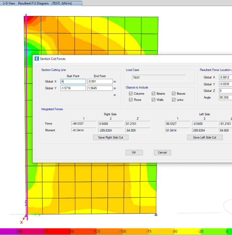
As for restraints issue you mentioned, I used the default setting 'Add Restraints on Edge if Corners have Restraints' so where the mesh nodes are the restraints were already applied. This can be verified by the reactions shown below.
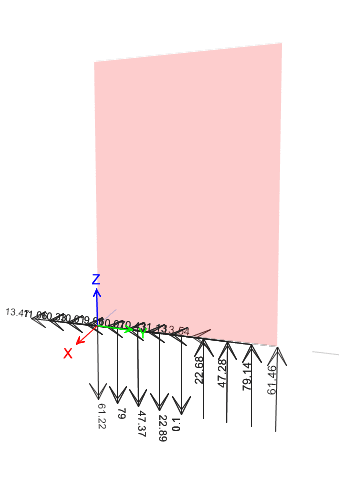
That said, I have split the shell into 10 to create more restraints and I also reduced the mesh size.
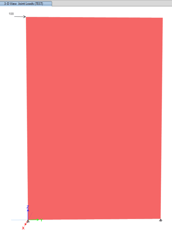
As suggested, I changed the loads from point load to a 50kN/m line load on top by using 100x100 dummpy beam.
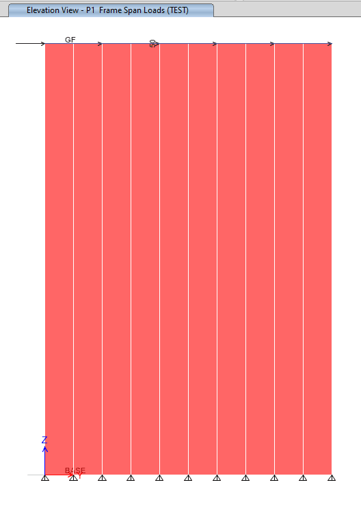
Still, I have around 30kN/m shear at the edge.
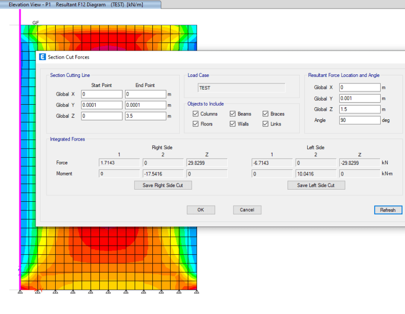
As for restraints issue you mentioned, I used the default setting 'Add Restraints on Edge if Corners have Restraints' so where the mesh nodes are the restraints were already applied. This can be verified by the reactions shown below.

That said, I have split the shell into 10 to create more restraints and I also reduced the mesh size.
As suggested, I changed the loads from point load to a 50kN/m line load on top by using 100x100 dummpy beam.

Still, I have around 30kN/m shear at the edge.

- Thread starter
- #8
-
1
- #9
By having a series of pin supports along the bottom edge, you are forcing the shear strain in the wall to be basically uniform at the base, which is why the bottom edge is mainly orange coloured. I believe a series of springs in the horizontal direction would get you somewhere closer to the theoretical elastic shear stress distribution (i.e parabolic) at the base.
Likewise, at the top of the wall, you have applied a uniform line load which does not reflect the shear stress distribution in an elastic beam.
Towards the middle this obviously gets somewhere near the elastic behaviour of a beam, which is Saint Venant’s principal in action. Same thing when you applied a concentrated load in the initial case.
"But both SCut3 & SCut4 shows non-zero force F3 in your model as well." Hmm, too early I guess.
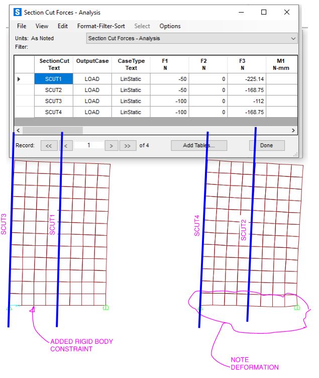
I think gusmurr is on the right track. I altered the base constraint using a fixed connection and beam element at the base. By altering its dimensions of the beam the F3 value is nearing the solution, but not quite correct.
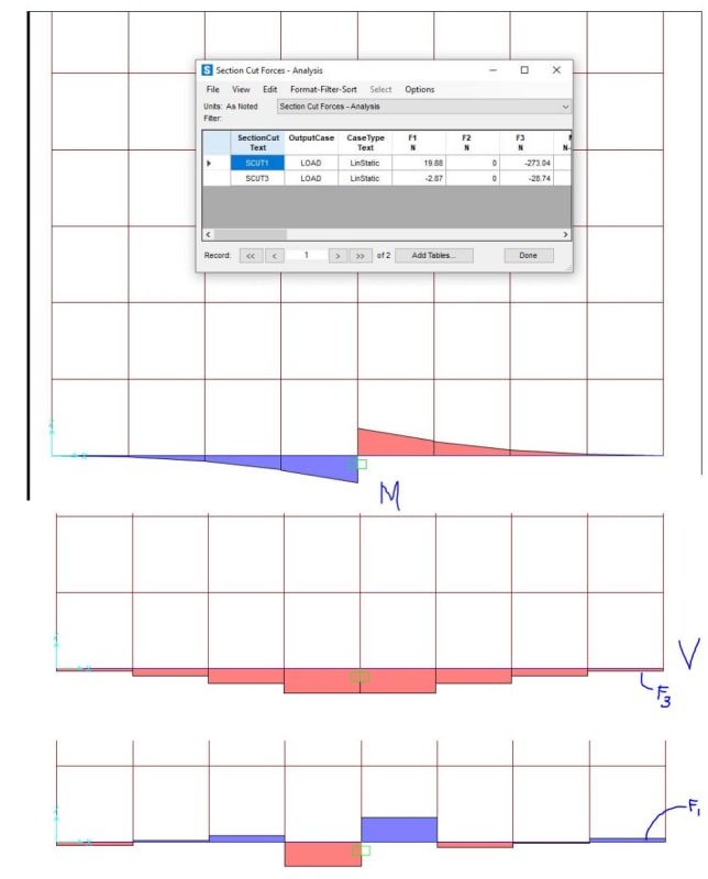
By refining the mesh the result is closer to correct. I am out of time for this thought exercise.
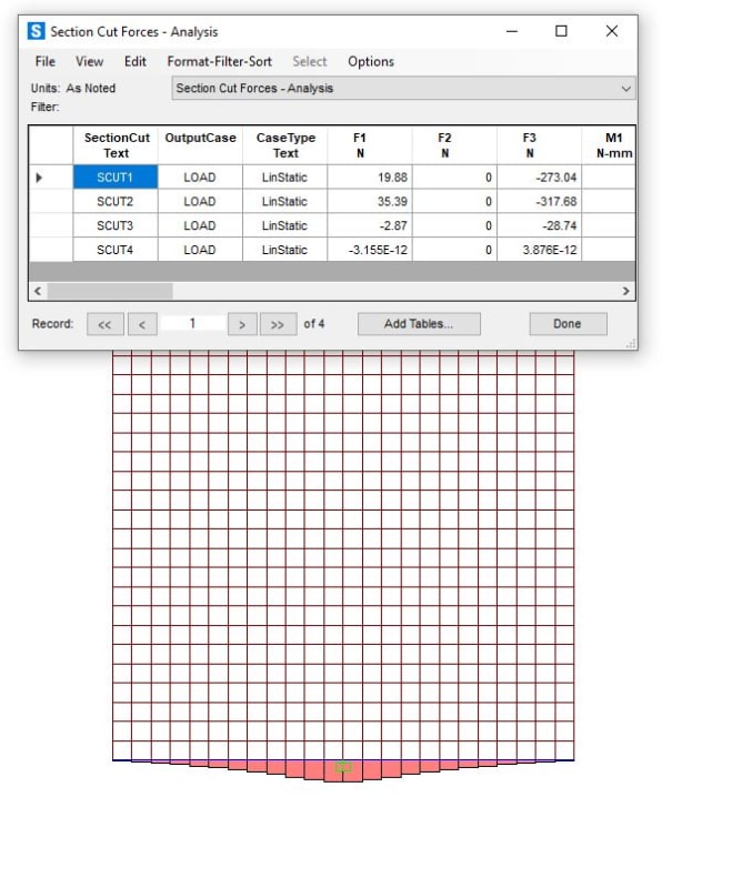
I think gusmurr is on the right track. I altered the base constraint using a fixed connection and beam element at the base. By altering its dimensions of the beam the F3 value is nearing the solution, but not quite correct.

By refining the mesh the result is closer to correct. I am out of time for this thought exercise.

- Thread starter
- #12
- Thread starter
- #13
- Thread starter
- #14
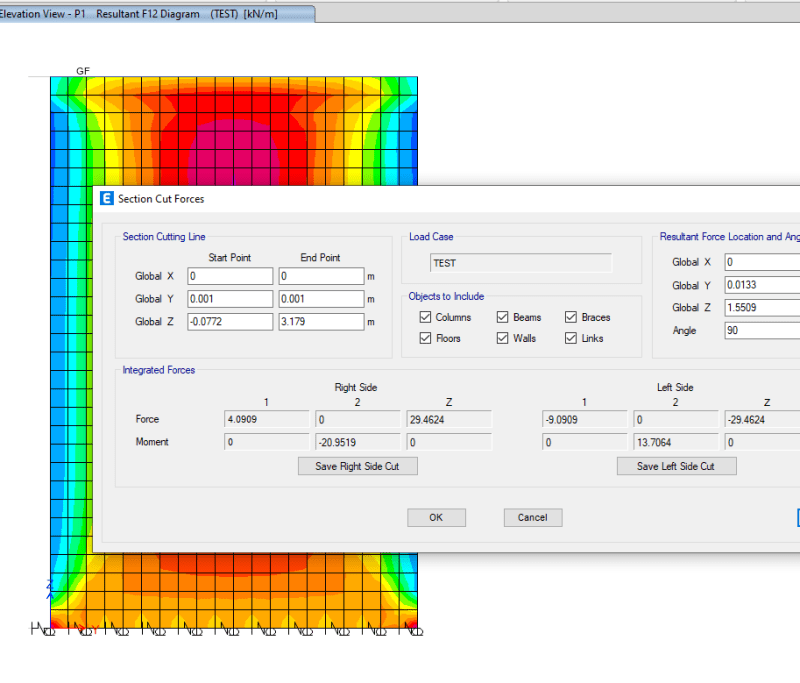
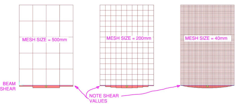
I only have a fixed joint at the middle of the wall. There is a very stiff zero mass beam across the base to replicate the fixity. You can see the shear in the beam is approaching what gunsmur describes as the mesh is refined.
Model images
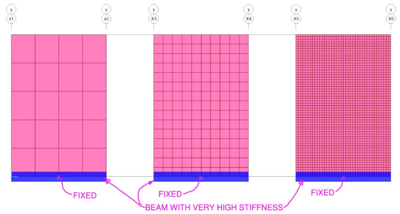
Shear in beam.
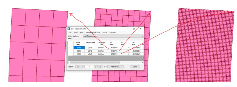
Comparison of the deflection of the fictitious wall.
Section cuts comparisons using the beam at the base compared to pinned base walls with varying mesh density.
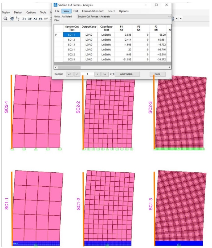
Reducing the mesh density in SC1-3 a little more the F3 value is 0kN. Obviously not a practical approach, but mesh sensitivity can be important depending on the goal of your analysis.
Model images

Shear in beam.

Comparison of the deflection of the fictitious wall.

Section cuts comparisons using the beam at the base compared to pinned base walls with varying mesh density.

Reducing the mesh density in SC1-3 a little more the F3 value is 0kN. Obviously not a practical approach, but mesh sensitivity can be important depending on the goal of your analysis.
- Thread starter
- #16
Thank you very much Brad.
I can see from your last picture that you have a model without base beam but multiple pin supports. What is the shear result for this model? Is it close to zero as well?
I expected the spring conditions give me results that are closer to theoretical ones but turned out not quite so mentioned earlier.
- Thread starter
- #17
I did divide the elements in SC2-3 by two and the F3 value you are interested in changed from 16.7kN to 5kN. One would never do that in practice, so it is merely a thought exercise.
I think you need to ask yourself what you expect for forces in a panel like this? The dimensions of this are more like a squat wall rather than a flexural element. There have been many FEA studies where they have replicated actual test data using NLFEA methods. Study
I think you need to ask yourself what you expect for forces in a panel like this? The dimensions of this are more like a squat wall rather than a flexural element. There have been many FEA studies where they have replicated actual test data using NLFEA methods. Study
- Thread starter
- #19
Thank you Brad. I am looking at the last picture you uploaded and I can see the F3 in your SC2-3 is around 31kN, which is similar to mine and I believe the mesh size if your SC2-3 is small enough but don't know why a close to 0kN result is still not achieve even if I assign spring instead of restraints.
I am trying to find the shear flow in my built up section for my connection design. For example, if you have a cantilever beam of which section is a built-up box. How do you get the shear along the connection for your fastener design? I know we can use q=VQ/I to get the shear flow but it seems a time-consuming process to me especially when the built up section becomes complicated. So I am looking for a FEM way to do the work. So I start with this simple rectangular section to see if it matches the theoretical result before I move to a complex section. How would you calculate the shear flow without using hand calc? I know I can define a built up section and assign it to a frame but it doesn't give me the shear flow I want. Using the shell stress seems the only way to me.
- Status
- Not open for further replies.
Similar threads
- Replies
- 19
- Views
- 25K
- Locked
- Question
- Replies
- 1
- Views
- 2K
- Question
- Replies
- 17
- Views
- 2K
- Question
- Replies
- 1
- Views
- 9K
- Replies
- 5
- Views
- 3K

