Continue to Site

Eng-Tips is the largest engineering community on the Internet

Intelligent Work Forums for Engineering Professionals

  • Congratulations KootK on being selected by the Eng-Tips community for having the most helpful posts in the forums last week. Way to Go!

STM

Status
Not open for further replies.

Shze111

Structural
Sep 21, 2021
4
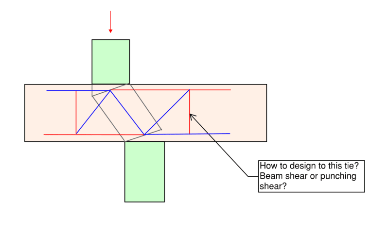
I am using STM for this offset column to flat slab analysis and design and wondering how to design to this vertical tie? If I use one way shear Vu will not be sufficient so I have to use vertical ties. However it doesn't convince me that I need vertical tie here. The reason being, if the column above does not overlap with the one below, the punching shear capacity from the concrete can take this transfer load (say 1500kN) without using ties. Thoughts?
offset_column_bqvyac.png
 
Replies continue below

Recommended for you

Your model needs to extend to each end of the slab you've shown, which is the extent of the D-region, and be in equilibrium with the forces there and in the coulumns (including moment and shear). I'm not sure you've done that.
 
Thanks for your response.
I can extend the truss model depending on the end condition of the slab. Refer below as an example.
However, my intention here is to solve the equilibrium by hand and that's why I made the above simplified model.
The question I have here is how do I design to vertical tie force? Like I said, the concrete punching shear capacity is sufficient to take the transfer load if the column is completely offset without overlapping. Now it doesn't make sense to me that I will have to use ties when the column is partly overlapped with the one below? By doing this STM I am forcing the slab to behave like a beam, which is not true? Should I compare the vertical tie force with the slab punching shear capacity by assuming the perimeter to be 4*d where d if the effective depth of the slab instead of using the one way beam shear capacity assuming the cross section to be d * column depth?

5666666_zshojs.png
 
However, my intention here is to solve the equilibrium by hand and that's why I made the above simplified model.

That's not how STM works. You go in knowing the boundary conditions from some other analysis.

Like I said, the concrete punching shear capacity is sufficient to take the transfer load if the column is completely offset without overlapping

What column moments are you using in the punching check? You don't show any on the STM diagram. This comes from analysis of the building as a whole, or at least a larger portion of it.
 
I understand what you mean but the slab is going to be designed by contractor. I am just checking the D region non flexural design and the end condition varies. If I develop the full truss model considering supports at far ends that will be too much work and it is thus not my intention.
I just found similar question raised in this thread as well.

So I have the column axial force and moment from the full 3D model and checked the punching shear and the slab passed without ties. Now I am just trying to create a STM near the support.
 
"If I develop the full truss model considering supports at far ends that will be too much work and it is thus not my intention. "
Your intention as an engineer should be to design according to sound engineering principles based on empirical and theoretical knowledge - not to "minimize work", whatever that means. If you have insufficient information to design correctly, you should inform your superior and request the information required to complete the design.
 
I dont think I am minimizing work here. No one is going to use strut and tie for the full flat slab design, would you?
Like I said, my intention here is to design the D region due to offset column by using strut and tie. I can develop different Strut tie model to suit but the question here is after getting the vertical tie force how do you design to it.
 
Take your latest model. The node at the bottom of the tie in question isn't in equilibrium. The tie pulls it up and nothing else resists the upward force. If you do the full model to the D-region boundary, there would be another compression diagonal representing slab shear. You say you don't need shear reinforcement in the rest of the slab, but suddenly the tie force means you need it here which suggests the boundary force is smaller and therefore the btm node still wouldn't be in equilibrium.

At a minimum, you need the boundary moments and shears in the slab and columns to do this design, regardless of who designs the slab. The column compression force won't be on the column centreline due to these moments, and the slab moments will tell you the magnitude of the tension/compression forces there. The slab shear is also a clue as per above.
 
Status
Not open for further replies.

Part and Inventory Search

Sponsor