Continue to Site

Eng-Tips is the largest engineering community on the Internet

Intelligent Work Forums for Engineering Professionals

  • Congratulations KootK on being selected by the Eng-Tips community for having the most helpful posts in the forums last week. Way to Go!

Increasing a truss' buckling capacity locally

Status
Not open for further replies.

nivoo_boss

Structural
Jul 15, 2021
130
Hey everyone!

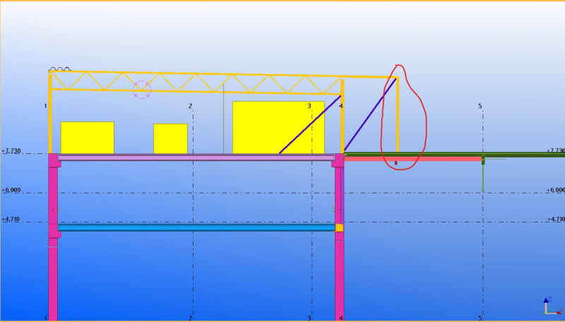
So I have this frame where I cannot have any brace members and also cannot have rigid column supports. So I'm thinking about making the frame's top joint rigid by connecting the truss's both chords with the columns and this way I can get a sway frame. The columns are SHS square sections and the truss on the pic is also made from SHS steel sections. I do not want to use an I-beam since it would be over 2x heavier at this span (~13 m) than a truss.

It's a small room (~6 x 12 m) for HVAC units etc and it's also quite low (around 4 m).

Ignore the right side of the frame - the right most column actually has a vertically sliding support and the diagonal is for supporting the top beam - the right side is basically a hanging structure over an existing roof for housing pipes etc.

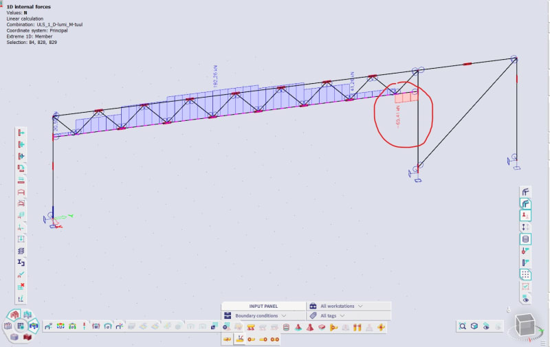
To my question finally. As you can see from the pic a compressive force of around 65 kN develops in the bottom chord of the truss at the last section.

Now the buckling length of the bottom chord is the same as the span (~13 m). And taking a compressive force of 65 kN at that buckling length takes a pretty large section. So my question is this - could I make the section just bigger at that last stretch of the chord by welding a thick steel plate under the SHS section for example and then would use that section's second moment of area to calculate it's buckling capacity at a buckling length of around 13 m?
truss_e8junf.jpg
 
Replies continue below

Recommended for you

OP said:
So my question is this - could I make the section just bigger at that last stretch of the chord by welding a thick steel plate under the SHS section for example and then would use that section's second moment of area to calculate it's buckling capacity at a buckling length of around 13 m?

I would say that no, you cannot do that. You can't just beef up the section locally and then assume that same section's properties apply to the entire length of the bottom chord for buckling. The entire length of your bottom chord will be involved in the buckling mode shape even if it is only that last panel that is actually in compression.

Some options for resolution:

1) Laterally brace the last bottom chord panel point such that you can design the segments of bottom chord on both sides of that joint separately and, therefore, reinforce locally.

2) Do an FEM buckling analysis with or without your local reinforcement to attempt to exploit the fact that very little of your bottom chord is in compression.

3) Conservatively increase the size of your entire bottom chord.
 
As KootK notes, likely the only way to do it is to extend the bottom chord and design the top and bottom chord as moment elements. there is no manner that you can 'beef' up the top chord connection to develop the moment.

Rather than think climate change and the corona virus as science, think of it as the wrath of God. Feel any better?

-Dik
 
I should add that the lateral bracing option that I mentioned above (#1) is my favorite by far. It's robust and may well obviate the need for local reinforcing altogether.
 
"I should add that the lateral bracing option that I mentioned above (#1) is my favorite by far. It's robust and may well obviate the need for local reinforcing altogether."

Yes, if I could brace it, it certainly would not need any reinforcement. The thing is, I don't have room for laterally bracing it - if I did I probably wouldn't be asking here for help :) Most of the space in the room is used by the equipment or pipes etc. Anyway, I did a quick buckling analysis as you suggested. I did not use a reinforced segment in the end. And the results - it does not buckle, at least not in the first 25 modes :D I guess it kind of makes sense, since most of the chord is in tension.

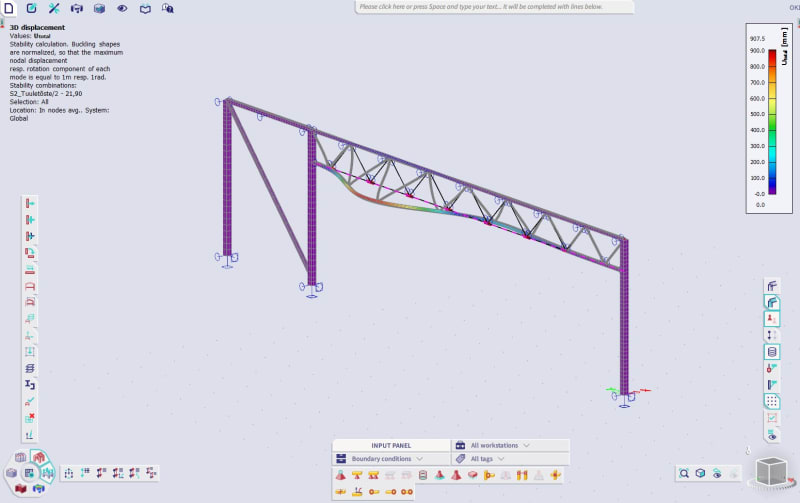
Just to check I also did a buckling analysis with another combination, where wind lift is the governing load and most of the bottom chord has some compression - and the result is below - the second mode buckles the bottom chord:

truss_buckling_crtymj.jpg


But anyway, back to my first problem. Since it does not buckle, what should I do?
 
I would find the elastic buckling stress from your models (multiply whatever the force is in the model by the buckling factor), and plug that into aisc 360 in place of Fe, and then do a hand calc for the bottom chord for whatever forces it sees. That gives you a shot at capturing inelastic effects, to the extent they are captured in the code.
 
You need to come to a design conclusion. One of the following would do:

- Find the buckling load and check capacity. You could run more buckling modes or do an alternative calculation.

- Determine that the uplift case is going to govern. You might have enough information already available.

- Make a qualitative judgment of adequacy.
 
nivoo boss said:
Just to check I also did a buckling analysis with another combination, where wind lift is the governing load and most of the bottom chord has some compression - and the result is below - the second mode buckles the bottom chord:

Why should we believe that?

BA
 
Can't you brace the truss to the roof by stiffening the web and connecting rigidly to roof members so it can't roll over? Like how pony trusses work?

 
By the book, you need to rationalize your buckling analysis to be compatible with the requirements of your local code. Member Agent666 has an excellent blog post on how that kind of thing is done: Eng V Sheep

If you can't manage a fly brace, another option is shown below. Sort of a strongback approach. You'd want a connection between the truss chord and strongback that allows for axial slip. If you've got the buckling analysis working, however, that's surely a cleaner and more cost effective solution.

c01_j8popo.png
 
I like Kootk's option. It provides a lateral brace at the first (and second) panel point of the truss.

BA
 
I believe that this is Tomfh's proposal. If so, I agree, it does have curb appeal.

EDIT: upon a closer read, I think that Tomfh proposes using the truss web itself for the vertical in the pony frame thing. Similar concept.

c01_lwzgcn.png
 
KootK said:
By the book, you need to rationalize your buckling analysis to be compatible with the requirements of your local code. Member Agent666 has an excellent blog post on how that kind of thing is done: Eng V Sheep

If you can't manage a fly brace, another option is shown below. Sort of a strongback approach. You'd want a connection between the truss chord and strongback that allows for axial slip. If you've got the buckling analysis working, however, that's surely a cleaner and more cost effective solution.

Sorry, I don't get it. The left most column on my screenshot has a vertically sliding support, the triangle there is sort of a cantilever.

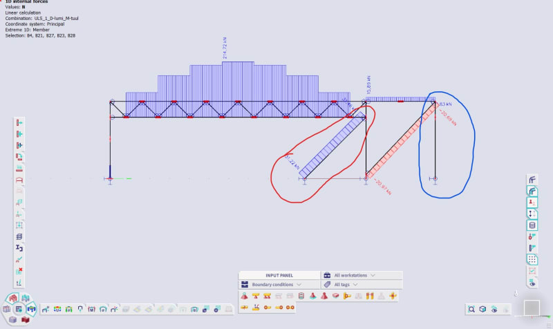
Anyway, I think I got a working solution without connecting the bottom chord of the truss with the columns and this way no compression develops in the chord on vertical loading. The problem with using bracings in the wall was that it would be connected to the roof below which is 320 mm thick hollow core roof with a span of, well, 13 m, and the reaction from that bracing would kill the slab. However, if I use that bracing in tension, it is okay, since the load on the hollow core would be upward. See the screenshot below, I highlighted the tension brace in red and in blue I show that the right most column has basically zero axial force since it hangs on a pre-existing roof.

truss_with_a_bracing_bsucyu.jpg


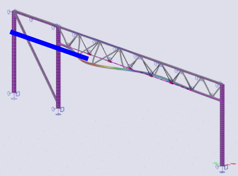
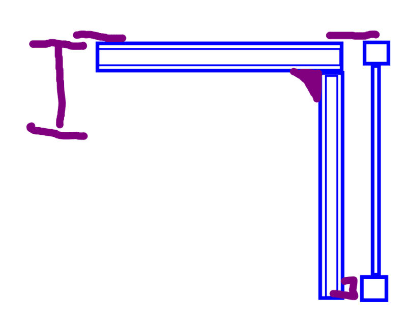
In the second picture I highlighted the zero-force column again and the picture should make the situation a bit clearer overall. Basically it hangs on a load bearing sheet roof that certainly cannot take that sort of point load - that's the reason it hangs. In purple in the model is the hollow core slab I mentioned.

truss_tekla_b0gykw.jpg
 
Kootk said:
EDIT: upon a closer read, I think that Tomfh proposes using the truss web itself for the vertical in the pony frame thing. Similar concept.

Yes I was imagining making the web members sufficiently stiff and using them as the stabilising members, fixed into the roof system.
 
nivoo boss said:
What? Why the hell would I lie about such thing?

I was not suggesting you lied, but perhaps that you were mistaken.

nivoo boss said:
Just to check I also did a buckling analysis with another combination, where wind lift is the governing load and most of the bottom chord has some compression - and the result is below - the second mode buckles the bottom chord:

If the bottom chord is hinged to the column at each end, then under wind uplift, I would expect first mode buckling. Second mode buckling could occur if the inflection point is laterally braced, but it's not.

BA
 
Member Agent666 has an excellent blog post on how that kind of thing is done: Eng V Sheep

Thanks for the plug, I'd start at part 1 for the complete experience. All parts here for those interested:-

For design to AISC, once you have the buckling load, you can back calculate the critical stress. Then use this in place of the equations in the code for the critical buckling stress. Then the design proceeds as per "normal".


Agent666 said:
Thanks for the plug, I'd start at part 1 for the complete experience. All parts here for those interested:-

For design to AISC, once you have the buckling load, you can back calculate the critical stress. Then use this in place of the equations in the code for the critical buckling stress. Then the design proceeds as per "normal".

Thanks, I'll check it out. I work with Eurocodes, but that shouldn't make much difference.
 
Status
Not open for further replies.

Part and Inventory Search

Sponsor