Continue to Site

Eng-Tips is the largest engineering community on the Internet

Intelligent Work Forums for Engineering Professionals

  • Congratulations waross on being selected by the Eng-Tips community for having the most helpful posts in the forums last week. Way to Go!

Sizing coped beam fillet and electrical continuity in steel structures 1

Status
Not open for further replies.

RabitPete

Structural
Nov 24, 2020
109
US
I could not find any code reference to the minimum fillet size when designing coped beams. Which version on the pic below do you guys like more? Those are normally laser or plasma cut from 2 directions, so they rarely match perfect and typically leave some stress concentrators anyway

And sort of unrelated question: I was inspecting one of the projects last week and noticed that steel erector was cleaning off the shop coat on the mating surfaces, they told me its to improve electrical contact. Never seen it done before, does it really make any difference since some of it gets scratched anyway, especially under fasteners, and would not it be detrimental to corrosion protection?
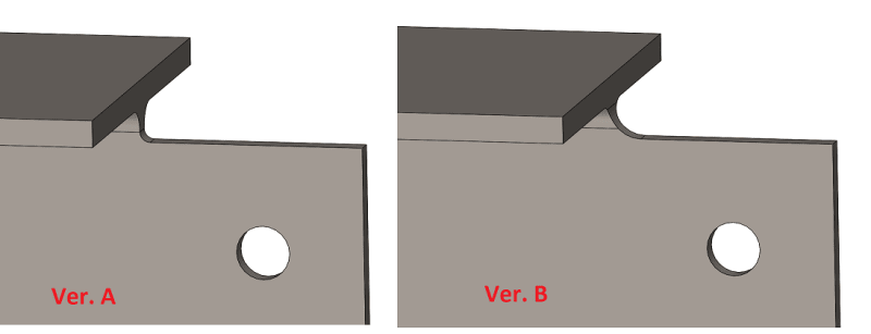
cope_vnvbu9.png
 
Replies continue below

Recommended for you

AISC defers to D1.1 for this I believe, which is generally a minimum radius of 1/2". (Page 9-19 of the 15th ed. SCM states, "All re-entrant corners must be shaped notch-free, per AWS D1.1, to a radius. An approximate minimum radius to which this corner must be shaped is 1/2in") If it needs to be designed for fatigue, Appendix 3, Table A-3.1 (of ASIC) would apply where a radius of >=1" is required for stress category C and a radius >=3/8" gives you stress category E'

I would think that Ver. B with the larger radius would be better for stress/fatigue purposes. I'm not sure if there would be any negative impacts for having the transition in the "k" area.
 
Thanks dauwerda

Rather than think climate change and the corona virus as science, think of it as the wrath of God. Feel any better?

-Dik
 
What type of structure is it? Why would they need to improve electrical contact? That sounds more like preparing the faying surfaces for a slip critical connection.

If electrical contact (for grounding?) truly were needed, I would say the cleaning primer off would be necessary to ensure a good contact, I wouldn't count on scratches to provide a good connection.
 
dauwerda said:
What type of structure is it? Why would they need to improve electrical contact? That sounds more like preparing the faying surfaces for a slip critical connection
It is a 3 story office/commercial building, there are no slip critical connections on the plans. Contractor said they always do it to ensure electrical contact for proper grounding. I've never seen it done before on similar structures and nobody does it on PEMBs either, yet framework is always assumed to be grounded. Those faying surfaces are never perfectly flat and in reality touch only in a few spots once tightened, sometimes you can even see the white light through the gaps. Would removing a shop coat just cause possible corrosion issues later on?
 
dauwerda said:
AISC defers to D1.1 for this I believe, which is generally a minimum radius of 1/2". (Page 9-19 of the 15th ed
I am looking at 2015 version of D1.1 and its section 5.16, it does specify 3/8" for the weld access holes but nothing for copes other than "Beam copes and cut surfaces in connection materials shall be free of sharp reentrant corners." So 3/8in should probably be a safe minimum for copes on statically loaded beams.

C5.16 states "The code does not specify a minimum radius for corners of beam copes of hot-rolled beams or welded built-up cross sections because any arbitrarily selected minimum radius would extend up into the beam fillet or the bottom of the flange, in some cases, making the radius extremely difficult or impossible to provide. Further, the peak stress can be accommodated only by localized yielding, and the magnitude of the elastic stress concentration factors is not significantly affected by the differences in radii of any practical size."

So is it bad if it extends up into the k-area as sketched in version B? That was a 3/8" by the way, small beams, don't have much room to work with here. It sounds to me that for static loads radius is much less important than fabrication quality.
 
Any of the stuff I've seen where 'real' conductivity is requiired, all the parts are connected by cadweld or attached 'grounding lugs'.

Rather than think climate change and the corona virus as science, think of it as the wrath of God. Feel any better?

-Dik
 
If it's a life safety issue, I tend to be a little conservative.

Rather than think climate change and the corona virus as science, think of it as the wrath of God. Feel any better?

-Dik
 
Found this on YouTube and looks like all of the faying surfaces are cleaned to the bare metal Link

In our case it was not called by the drawings and out of state erector chose to do it since that's what they always do. I just personally never seen it done before and was concerned with the corrosion and water being trapped in the joints. Since AISC allows enclosed interior steel to be left unprimed and unpainted, its probably not an issue.
 
Check out the cope quality @2:30-2:31 mark Link What are your thoughts about the beam on the left?
 

It's about as ugly as I've ever seen (don't think I've seen anything as ugly).

Rather than think climate change and the corona virus as science, think of it as the wrath of God. Feel any better?

-Dik
 
Status
Not open for further replies.

Part and Inventory Search

Sponsor

Top