Continue to Site

Eng-Tips is the largest engineering community on the Internet

Intelligent Work Forums for Engineering Professionals

  • Congratulations GregLocock on being selected by the Eng-Tips community for having the most helpful posts in the forums last week. Way to Go!

Cantilever Pile Cap STM

Status
Not open for further replies.

Brad805

Structural
Oct 26, 2010
1,493
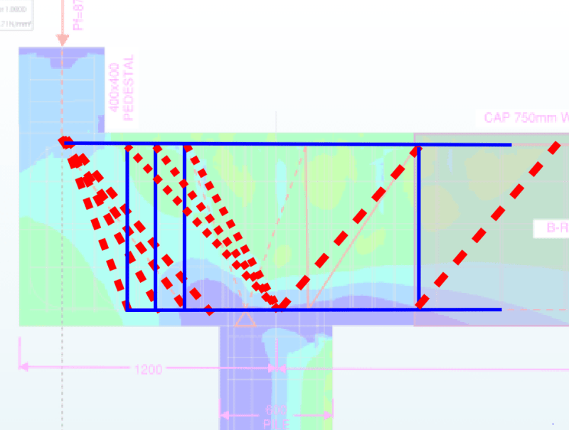
I am working on a building project where there are some piles that cannot be installed directly under the building columns. I am looking at a cantilever pile cap solution as sketched below. I have sketched the STM model over one of the stress diagrams. Is this STM model reasonable or could it be improved?
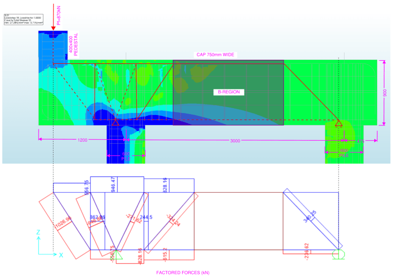
STM-Q_ifltqr.png
 
Replies continue below

Recommended for you

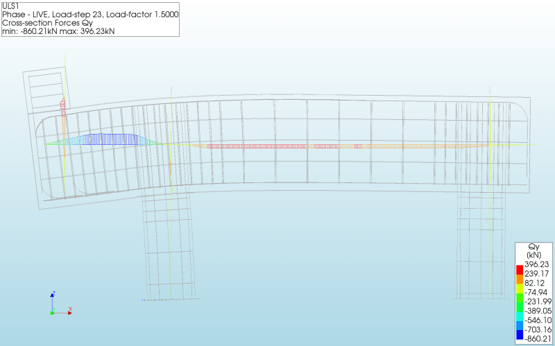
Thanks canwesteng. Without a tie left of the pile in the STM would you detail ties? The shear is 860kN in this region. I based the layout on the study attached. We usually have endwall framing where we abut the existing building, so this atypical for me.
STM-shear_lvmga6.png


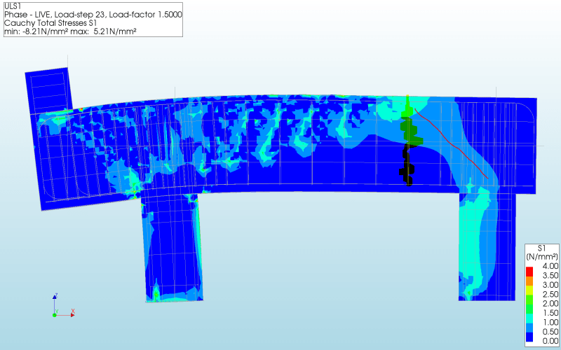
I included a stress plot of the principle tensile stresses below. I aligned the right tie based on that. In the model I had missed the highlighted tie, and the cap broke right above the point where that tie intersects the top plane of the cap.
STM-2_odfzef.png
 
I would have stirrups left of that pile regardless, but your detail above to put a tie there is good too. I looked at it and thought 900/1200=35 degrees, but once you account for strut and ties depths it is shallower so maybe your original detail is better. You certainly could put a diagonal tie there to match your FEA, but as long as the STM works you've provided a valid lower bound to the strength of the pile cap and it wouldn't be necessary, although it would result in less cracking.
 
I usually detail so there are only diagonal struts, not ties. IMO this is more consistent with how we design B regions as well.

I agree. The reinforcing in the structure needs to be oriented and located the same as the tension ties in the model. So unless there's going to be diagonal reinforcing ties in the structure (which is not the typical way to reinforce a pile cap), there shouldn't diagonal tension ties in the model.

Rod Smith, P.E., The artist formerly known as HotRod10
 
I usually design these as deep beams so that I don't end up with any weird bar arrangements that arise from STM
 
Arranging the STM so that ties occur in the vertical direction is great. However, particularly for deep beam regions that will see some requirement for horizontal ties in the D-region anyways, inclined ties can be created in the aggregate of more easily built components of vertical and horizontal steel.

----
just call me Lo.
 
1) A likely inaccuracy in your model is that it shows the column rotating along with the beam end. In many situations, the column probably tends to remain more vertical and your strut runs from the inside face of your column to the outside face of your pile. This would tend to make for a steeper strut that could potentially work without vertical ties in the cantilever.

2) In a situation like this, I'll usually put a vertical tie in the cantilever anyhow for belt and suspenders. That said, I smear out the ties such that there is not so much a discrete gaggle of them just in front of the pile. The stirrups just are the ties. Done this way, deep beam design and strut and tie design effectively yield the same outcome, as they ought to. The STM that would apply to this story is shown below. The struts to the right of the pile would also normally be smeared. I was just too lazy to follow through on that.

C01_ajwncx.png
 
Thank you for all the helpful comments.

I revised the model to use a thick bearing plate with a pin/roller support like most of us like. This is likely more correct since I had only used a 1.0m pile length earlier. These are 40'-0" deep piles, but the fixity point will be deeper than 1.0m. I had an interface at the base of the pile, but it was too stiff after looking a bit more.
STM-5_syqg8i.png


There are only three of these needed, so I am on the same page about the extra ties. I was curious how friendly others are to the rod busters.

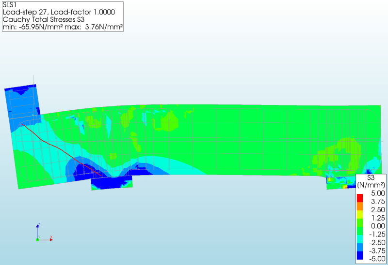
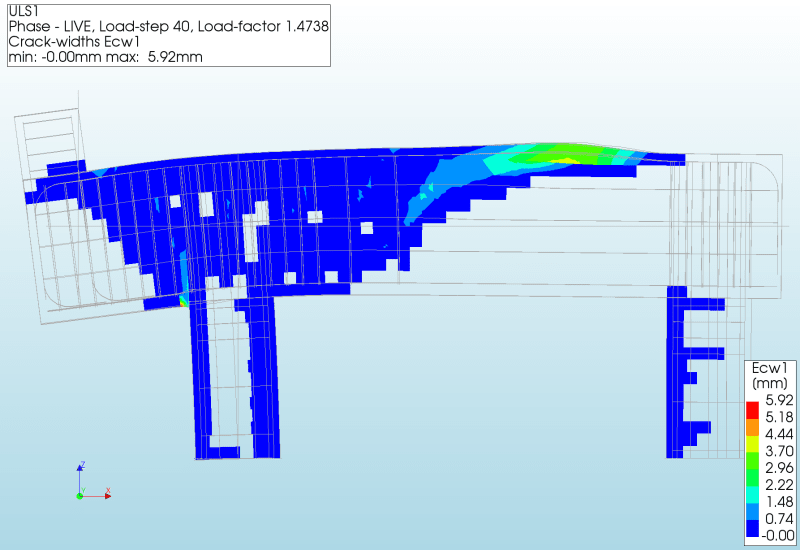
To illustrate the reasoning behind the tie on the right hand side I re-ran the model after deleting a number of ties and reducing the size of the top bar to the minimum to satisfy the top tie force. I was planning to smear ties instead of odd rebar, but given the thickness of the cap one could easily tie the diagonal bars. This is the ULS load case, so the values are only to illustrate what might happen. This model does not converge correctly in the later load steps, so it is not something I would use for design.

Cracking as at an early load step.
STM-3_gamlcw.png


Cracking at 1.25D + 1.47L. Here you can see the primary crack starts at near the B-region/D-region intersection.
STM-4_btxn9k.png
 
Status
Not open for further replies.

Part and Inventory Search

Sponsor