Continue to Site

Eng-Tips is the largest engineering community on the Internet

Intelligent Work Forums for Engineering Professionals

  • Congratulations waross on being selected by the Eng-Tips community for having the most helpful posts in the forums last week. Way to Go!

Shear Flow at Vertical Beam Splice (Transverse vs Horizontal Shear)

Status
Not open for further replies.

StrEng007

Structural
Aug 22, 2014
510
Got a theoretical question for you all!

We know that a beam will support internal transverse (vertical) shear stresses that act over its cross-section. The result of this shear is noted as V. Due to complementary properties, transverse shear has a corresponding longitudinal (horizontal) shear stress. This is made evident by shear flow equations used for built up members where we determine shear forces and resolve them with the use of fasteners, welds, etc.

For beams splices such as a steel W-Beam, serval options are available to provide moment and shear continuity. One popular option for transverse shear is the use of web plates. This is often resolved by considering the number of bolts required to support the internal transverse shear (V) in addition to the torsion (Ve) caused by the splice offset to the bolt group centerline (where eccentricity is noted as e).

For the beam splice scenario, how does the longitudinal shear flow across the vertical splice?

Why isn't this addressed in most references on the subject?

 
Replies continue below

Recommended for you

Are you familiar with Bernoulli (B) and Disturbed (D) regions in the strut and tie design of reinforced concrete? If so, most steel connections are fundamentally like disturbed regions where one accepts that Bernoulli, plane sections remain plane assumptions don't really apply and the name of the game is primarily satisfying equilibrium within the connection.

When we do the VQ/It business, Bernoulli flexural behavior is baked into that. As such, it won't be strictly applicable at a typical shear splice. There will still be local demand for horizontal shear resistance around the connection but, because you're usually dealing with monolithic, non-welded web material for that, it tends to not be a meaningful design concern. Certainly, if you want to study some local FBD's around the joint, that is something that could be done.
 
I see what you're saying but I would need to review those concepts.

I'm glad you responded because this question is helping me establish some fundamentals for a timber beam splice. With timber framing not being my primary background, I was trying to first approach the theory from the comfort of a steel beam.

I've got large timber beam/rafters being spliced at locations of low to no (theoretical) moment. I was going to apply steel plates at each (side) face of the beam with lag screws for the transverse shear. I started to get concerned about horizontal forces in those bolts as I wasn't sure if there is combined influence in bolt shear both perpendicular and parallel to the grain.
 
My understanding is that the longitudinal 'shear' forces are the force couple (moment) producing longitudinal compression in some areas of the splice plates, and longitudinal tension in other areas. The moment produces forces in the bolts based on the polar moment of inertia of the bolt group. Is that incorrect? Am I looking at it too simplistically to answer the question?

Ah, sorry. I needed to reread your response, StrEng007.

I should add that the moment you're using in this case is the moment due to the eccentricity of the shear between the centers of the connections (bolt groups) on each side of the splice (shear x center-to-center distance between connections).

Rod Smith, P.E., The artist formerly known as HotRod10
 
OP said:
I was going to apply steel plates at each (side) face of the beam with lag screws for the transverse shear.

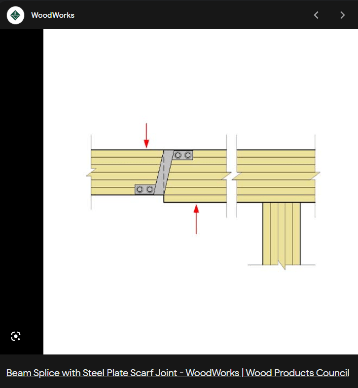
I don't love that particular connection type for this. If possible, it's often advisable to set these things up such that the shear is delivered to each member in bearing, similar to the detail below.

OP said:
I started to get concerned about horizontal forces in those bolts as I wasn't sure if there is combined influence in bolt shear both perpendicular and parallel to the grain.

I imagine that there would be horizontal forces in those bolts owing to the eccentricity of the shear delivery mechanism. Often, the parallel to grain resistance required of the bolts isn't too onerous when combined with the perpendicular to grain requirements.

c01_w9pn67.png
 
I agree with KootK on the preferred detail type.

StrEng007 said:
I've got large timber beam/rafters being spliced at locations of low to no (theoretical) moment.

I would advise you to remove the continuity from your modeling assumptions. Make the splice point a pin in your analysis and make sure moment transfer is not required at that point. Otherwise you could end up with an unstable structure.
 
KootK said:
If possible, it's often advisable to set these things up such that the shear is delivered to each member in bearing, similar to the detail below
If I use that detail, can I still apply moment plates top and bottom. Keep in mind, I've got these splices at places with very low moments. But who knows exactly how they'll lift this beam in place and there may be some moment developed under self weight during placement.

phamENG said:
Make the splice point a pin in your analysis and make sure moment transfer is not required at that point
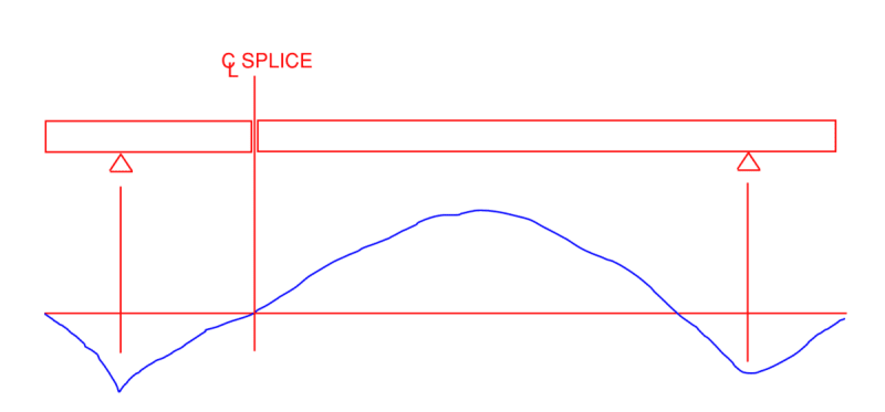
Can that be done along a propped cantilever beam? Even though I'm putting the splice at a point of zero moment I would still provide moment plates for continuity. If I did what you suggested, wouldn't that make the beam unstable?

See beam with moment diagram:
1_s8pjaa.png
 
With your latest sketch in mind, I believe that your splice will have to be a moment connection in addition to a shear connection. That, and you'll need to consider which partial load case produces the maximum flexural demand at the splice. This will be come a much more difficult problem given that moment connection in conventional wood construction are typically thought to be quite dubious owing to connection slop / slip and the fact that many of the best moment connections tend to spread out the fasteners in a way that restrains cross member shrinkage and induces cracking.
 
KootK,
I'm thinking of using a Simpson HCA hinge connector and dapping the top and bottom of the beam to create a flush mount. This would handle shear. Then I'd run moment plates over the top/bottom and create moment continuity.

 
Wouldn't touch that connection with a barge pole. Can't the glulam fabricator make the beam in one piece?
 
I'm with BA. No, thank you. That beam does not have a reliable point of zero moment anywhere in it's span. Why is the beam not being installed as a single piece?
 
Still working through it. I would include design for a minimum level moment but not the maximum moment the beam experiences.

Due to the roof configuration, the rafters need to be spliced due to available lengths. Good thing is, the utilization of the beam is very low. The beam is oversized due to exposure and architectural demands.
 
Status
Not open for further replies.

Part and Inventory Search

Sponsor