Continue to Site

Eng-Tips is the largest engineering community on the Internet

Intelligent Work Forums for Engineering Professionals

  • Congratulations waross on being selected by the Eng-Tips community for having the most helpful posts in the forums last week. Way to Go!

General tolerances on a drawing 1

Status
Not open for further replies.

Mannes Karsten

Petroleum
Nov 16, 2017
14
NL
Hi,

Quick question;

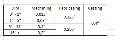
On an old rotor assembly drawing we received, there's a table with general tolerances ('unless otherwise specified'). Now in this tolerance table there are 3 columns: Machining, fabricating, casting.
I only know certain ISO-norms, such as ISO 2678-mK. I'm unfamiliar with the 'machining, fabricating, casting' tolerance table on a drawing.

What does the 'fabricating' column refer to? Is it to the assembly of parts? Does it refer to the fabrication of raw material? Something else?
 
Replies continue below

Recommended for you

Unless you post a picture, it's hard to grasp what's the matter.
 
I think 2768-2 is currently withdrawn.
Regarding your question, I would say your guess (of what fabricating means) is as good as mine.
Ask the drawing creator.
 
@Wuzhee:

Can't post a picture, best I can do is show a resemblance of the table:
2023-02-27_13_16_52-Book1_-_Excel_vlyku2.png


The values in above table are irrelevant/made up. But this is a resemblance of the general tolerances table on the drawing.
I'm looking for what the 'fabricating' column refers to.

Can't ask the guy who drew it, as this drawing is around 40 years old.
 
I'd guess based on tolerance value the fabrication column is an intermediate machining step where the blunt cast part will be premachined for later processing. This is where datum features are established usually to align the part later on in the fixtures.
 
@Wuzhee:

Thank you. I think it's indeed something along those lines.
One of our suppliers interpreted the 'fabricating' general tolerances as tolerance for the final assembly. And now the assembly doesn't fit due to the large tolerances specified in the 'fabricating' column.
 
"On an old rotor assembly drawing we received..."

"Can't ask the guy who drew it, as this drawing is around 40 years old."

Ask the source from which you received the drawing. Even if the guy who will answer is not the guy who drew it, whoever supplied that drawing should know what they need.
 
I haven't seen an assembly machining where such broad tolerances produced a good result. Even if it means assembly it's still open to questions. Too many questions.

These carry-over charts are the main enemy of modern machine shops in my eyes. I get the good intention of "loosen the tolerance so the machine shops can manufacture cheaper" thing, but sticking to lets say ISO 2768-mK is already cost effective so these custom tolerance tables aren't adding much value but confusion.
 
And just one last thought.
The customer wants a new rotor assembly for whatever item they produce. This rotor was designed 40+ years ago and still have it's 40+ years old drawing. The buyer gets the message "hey Joe we need this rotor, contact XY company and send them a PO".
Joe sends the PO along with the 40+ yrs old drawing. Contractor company's resp. receives the drawing, passed onto engineering/manufact. Eng/manufact checks the drawing, and there's confusion because it's old and outdated and has a lot of ambiguity in some places.
Contractor company reaches back to customer and says "Hey Bill, there's this old drawing you gave me to make this rotor but please clarify these sections because reasons". Bill checks and has no clue because he's only here since 2 years, gets an older guy to clarify but they still don't know. After some discussions they sit down and ask themselves: "Do we really need these old requirements or we should drop the old drawing and make one that actually makes sense in todays standard and spec?". They all agree, customer CAD guy makes a drawing, contractor receives new, unambiguous info, rotor gets machined, everyone is happy.
In that time, 2 month passed, customer had to delay delivery, contractor had unreliable machine shop schedule because they had to stop and start over, information passed among a few dozen people until it reached that one old guy who knew that the original chart didn't make sense even back then but it cemented itself into drawings, everyone shirks responsibility, frustration, tension, added costs etc.

Sorry, it just suddenly came together in my head, based on my experiences...
 
"Fabrication" = sheet metal bending or other forming operations.
 
The reason drawings exist like they do is that when they were made the companies that produced the parts knew what the end use was and had either been making similar parts for a long time or worked with the designers on this project. No one looked at these drawing tolerances because they were far larger than the variation that producing company would ever do. They probably had jigs and fixtures to keep variation to a minimum and the rate of producing working/usable items was so close to 100% you would be hard pressed to find a reject.

Then the buying company said - screw it - we don't need the design notes. No need to keep the correspondence with the original maker. We can free up some space and rid the place of all these file cabinets. They figure they have the drawings and that's all they need because that's all they sent with the original contract.

The best part - anyone updating this drawing likely has no engineering or design experience to know what requirements and limitations should be on the drawing. They will just put some glue and GDT glitter on it and call it a day.
 
I'd add welding in the fabrication definition.

I do like the idea of glue and GDT glitter...
 
Seems like fabricating is just about anything but casting and machining.
 
Status
Not open for further replies.

Part and Inventory Search

Sponsor

Top