Eng-Tips is the largest engineering community on the Internet

Intelligent Work Forums for Engineering Professionals

  • Congratulations waross on being selected by the Eng-Tips community for having the most helpful posts in the forums last week. Way to Go!

PEMB Transfer Station - Push Wall Design 2

Status
Not open for further replies.

Ben29

Structural
Aug 7, 2014
313
US
I am trying to come up with a fee proposal for a Waste Transfer Station. The job is basically a pre-engineered metal building foundation. But I noticed that they have what is called a "push wall". I did some research and I understand what it is.

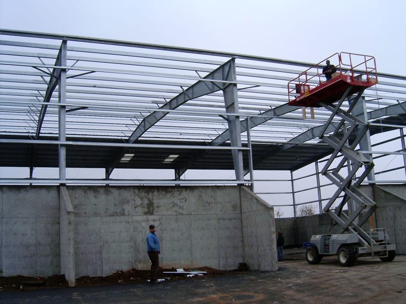
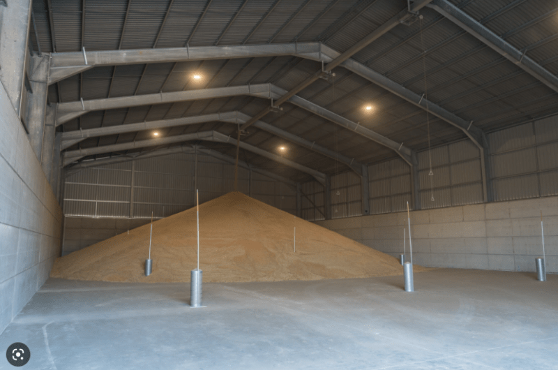
Looking at the preliminary layout drawings, it almost seems that the PEMB columns must bear on top of the concrete push wall. Is this normal? From my research it seems that the PEMB columns are usually outboard of the push wall, and the foundations for each are separate entities. Are they ever constructed with the columns bearing on top of the wall?

Below is a picture that I found online. ANd below that is a screen shot of the preliminary drawing elevation. I will ask the architect for clarity - but I wanted to run it by you all to make sure this isn't a "stupid question".
push_wall_1_vzppyg.png


push_wall_2_rlj45t.png
 
Replies continue below

Recommended for you

I haven't done one with a push wall before, however my thoughts are as follows:
1. Dealing with thrust from the PEMB is going to be a pain, most likely requiring pilasters.
2. Setting the columns outboard would simplify the project significantly for you, however I'm not sure if it would be cheaper to build.
3. My fee for this would be significantly more than a normal PEMB foundation and probably more than if I had just designed the whole structure myself conventionally.
4. PEMB anchorage to the wall will be difficult.
5. Definitely not a stupid question, they need to understand the impacts of placing the PEMB on top of the wall, from anchorage to thrust concerns. You will also need to know what the "push load" is as I assume this means they are pushing grains against the walls, so it's in essence a retaining wall with impact loading?
 
I think it is a good question. But I believe it will be more efficient to put the building columns on top of the push wall. I am not sure it is possible to have separate footings for the columns versus the push wall - the push wall is a cantilever wall with a large horizontal load at the top, so it will have a wide continuous footing.

DaveAtkins
 
Ben29,

I've done a few of these buildings with the PEMB columns on top of the concrete wall. We design piers inside the wall, as if the wall doesn't exist. We also take the thrust all the way to the footing and design the footing for the OT moment.

As for the push wall itself, we design it for the horizontal pressure due to the grain load (or manure, whatever's in your building). We do NOT design the wall for the front end loader to load the wall via pushing. If that's what's going to happen, well, thicken your wall accordingly. :)

Please note that is a "v" (as in Violin) not a "y".
 
Ben29, we've done this numerous times for Highway Maintenance firms. These buildings keep the snow and rain off of the sand and salt piles. The product is placed and removed with a front end loader.
As Aesur and DaveAtkins propose, we used pilasters to handle the thrust and anchor the PEMB on top of the CIP wall.
HPIM2179_g1aofn.jpg
 
WinelandV said:
We do NOT design the wall for the front end loader to load the wall via pushing.

Interesting. Perhaps it depends on the use. The one I designed (which had one of those arched fabric roofs) was at a waste transfer station, and I designed the wall for the front end loader pushing against the top of the wall.

DaveAtkins
 
Dave,

I'm sure it's a case of "here's what everyone from design to the owner agreed to" and "here's what actually happens in real life".

Please note that is a "v" (as in Violin) not a "y".
 
I saw one of these (in a plant that refined metal) that wasn't designed as a "push wall" initially. Long before I got there, they must have noticed a problem and braced it with angles. And lo and behold, the angles had failed (buckled) due to the loads pushing ore against the wall. No matter how big of a front end loader you design for, they're likely to get a bigger one.
 
I used the maximum hydraulic capacity of the bucket. The manufacturer literature usually shows that. As I recall, I considered it an ultimate load. I know I spread it at 45 degree angles down the height of the wall.

DaveAtkins
 
@DaveAtkins. Thanks for the tip. Komatsu gives max working pressure and bore for cylinders. Just multiply pressure * area * number cylinders?

Cat, john deere, kubota don't give bore on spec sheets though so not sure I'm looking at the right specs since you said usually available.
 
For retaining walls on highways a 50 Kip load is used and distributed along the impact width. So in this case the bucket width and then 45 degrees down for overturning and sliding.
 
The maximum load for the bucket would be the force required to flip the loader onto its back, pivoting at the back tires. At some force the cylinders holding the bucket will fully retract so the force they can supply hydraulically isn't the limit.

The limit to flipping is the traction due to friction between the tires and the floor.
 
I've designed for what the max friction between the tires and road surface could be.
 
canwesteng said:
I've designed for what the max friction between the tires and road surface could be.

Having seen a zillion of these buildings in real life.. this is probably the real-world approach to take. Conservatism is added by the fact that the floor of that building will never ever be clean and dry after the first day it opens.

This will wind up less conservative than the force required to flip the loader.. that's going to be a big number that in real life you'd never see (the loader isn't going to have enough traction to flip itself over backwards)
 
How about if the guys get really annoyed and decide to take a run up for a particularly stubborn pile of dirt....1.5 live load factor? [dazed]
 
Not sure these loaders can get going that fast, but if they are driving even half that recklessly, there will be huge chunks of concrete knocked out of your doorway in no time
 
Are you designing the areas in between the pilasters to take local impact loading? If say the loader backs into the wall. I am not saying I would or wouldn't..am just asking.

A few years back I watched a loader hit a wall pretty hard. He was trying to get unstuck...and when he got traction he shot into the wall.

 
Greenalleycat said:
How about if the guys get really annoyed and decide to take a run up for a particularly stubborn pile of dirt....1.5 live load factor? dazed

Ha! Well, unless the dirt pile is veeeeery small, the dirt won't move.
 
Status
Not open for further replies.

Part and Inventory Search

Sponsor

Back
Top