Continue to Site

Eng-Tips is the largest engineering community on the Internet

Intelligent Work Forums for Engineering Professionals

  • Congratulations KootK on being selected by the Eng-Tips community for having the most helpful posts in the forums last week. Way to Go!

Clamped Column 8

Status
Not open for further replies.

dik

Structural
Apr 13, 2001
25,736
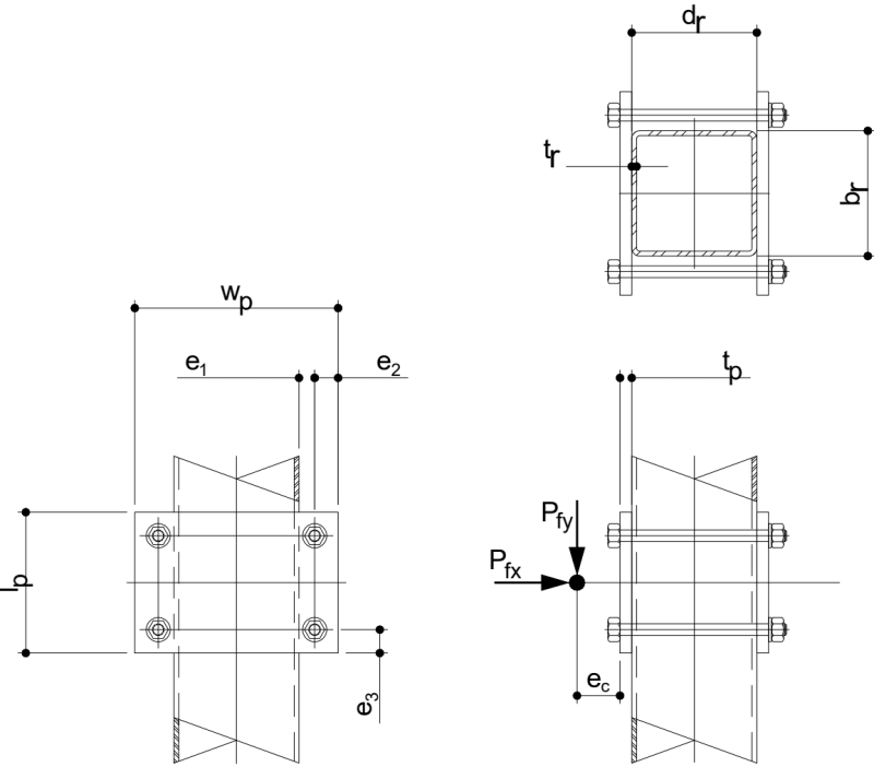
On a recent project, I require plates clamped to an HSS column with friction providing the vertical capacity. They don't want to drill or weld on site. I've attached a sketch of the connection. Any suggestions about maintaining the clamping force (my preference is Loctite Red) and determining the coeficient of friction? The material is HDG steel and the bolts are A325s. It is exposed to the elements and will probably cycle from -40C to +60C. One solution I haven't broached with the client is to use powder actuated fasteners with thinner clamping plates. I don't know if that is acceptable. I can easily calculate the crushing load of the HSS column walls.
Conn-Clamped_Col_bxeogy.png


-----*****-----
So strange to see the singularity approaching while the entire planet is rapidly turning into a hellscape. -John Coates

-Dik
 
Replies continue below

Recommended for you

Can you notch the columns with a grinder.
And weld a piece of flat bar on the plates.

Then the flat bar will engage with the notch in the column when you bolt them together.
 
Locktite will only keep the nuts from turning - retention of the clamp load is from elongation in the bolts, compression of the sidewalls, and some amount of flex in the plate. You are best off figuring out the smallest diameter bolt that will not crush/buckle the side walls to get the maximum elongation in the bolt. I would ensure the horizontal edges are chamfered to prevent digging into the pole, and maybe requiring a weather resistant bead of caulk on the top edge, though perhaps that is just too much reaction from seeing the results of salt-fog chamber tests.


In this case the connection shall be slip-critical . The faying surfaces be free of paint, grease, and oil, or a special paint be used.

Some points regarding coefficients ; EN1993-1-8 suggests μ ( varies from 0,2 to 0,5) and EN 1090-2 suggests μ=0.4 for Surfaces blasted with shot or grit and coated with alkali-zinc silicate or thermally sprayed with aluminium or zinc.

My suggestion would be , the paint on the faying surfaces could be removed with grinding and a seal paint with a brush could be applied all around of the faying surfaces after bolting.


I cannot give you the formula for success, but I can give you the formula for failure..It is: Try to please everybody.

 
I posted about a similar scenario a few years ago using clamped plates to resist vertical loads through friction. The general sentiment on that thread was to avoid as much as possible. I agreed with everyone at the time (and luckily it's not something that was implemented), and my feelings on that matter have only gotten stronger over the years.
 
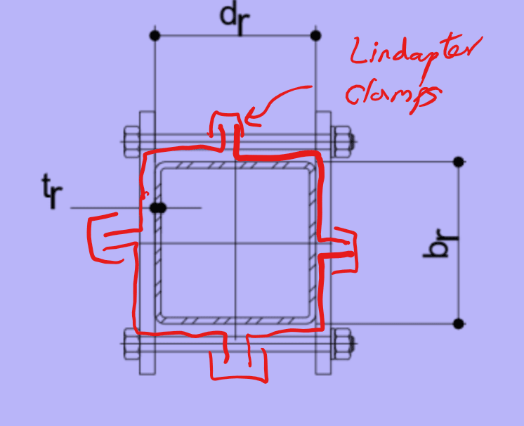
Think I'd be contacting Lindapter to see if they have done anything similar. My gut says with that temperature range, any solution will be difficult. How safety/stability critical is the connection? Using a fabricated half-box sections that could fail in slip, but then rotate and jam could give a 'fail safer' mode rather than two flat plates.

Screenshot_2023-04-11_133954-markup_cj0c2h.png
 
@Wrantler: Notching may be a possibility

@3DD: that was my main concern... relaxation over time. I hadn't thought of using the greatest elongation. Bigger is not better. The chamfered edges are a good idea, along with the caulk. Thanks very much.

@HTURKAK: My concern with slip critical was crushing tbe tube wall, but as 3DD noted to use the smallest bolt; I was thinking a larger diameter fastener. Thanks I wasn't thinking about elongaton.

@ST: Thanks for the caution; it may be unavoidable, hence, my inclusion of PAF.

@George: Thanks, I had not considered that type of fastener. I've not used them, but will take a peek.

Thanks very much, gentlemen. Next question, is there a high strength fastener that has great elongation? Any idea of what might be an appropriate coefficient of friction? Also, I write SMath programs for most of my problems, and will post it when I've got a solution. The sketch at the top was what I use in the programs for variables.


-----*****-----
So strange to see the singularity approaching while the entire planet is rapidly turning into a hellscape. -John Coates

-Dik
 
I sure like positive attachment... I'd cast a vote for PAF or some screws, although I suppose a self-drilling/tapping fastener is sort of still drilling on site.

Second thought - is your load eccentric as indicated in the sketch? That will naturally help the whole assembly from slipping along the column. I might feel slightly better about that.
 
If you can get your hands on the TIA-222 code, they offer some guidance for u-bolt friction connections which *may* be of use here. IIRC, square bend u-bolts too.

Have you looked at any of the structural adhesives?
 
@jittles: I may be a little... I don't know yet.

@azcats: I'll see if I can dig up some info on the TIA code...

-----*****-----
So strange to see the singularity approaching while the entire planet is rapidly turning into a hellscape. -John Coates

-Dik
 
This feels like one of those details where everything needs to go right and then it still only might work.

Isn't drilling a couple of holes way easier than than trying to get some sort of friction connection to work?
 
Yes jersey... I'm not thrilled about it and have some concerns, but before I discard the idea or modify it, I like to understand it. Currently looking at 1/2" dia bolts and chamfered edges.

I've often done 'wierd' connections, but like to know the problems. I've got coefficients of friction to use and the method seems plausible... but have to do a little work first. My current concern is the re-cycling loading... wind, snow and thermal.

I've not used them 'stacked' but I understand Belleville washers can be stacked for added 'tension'. Another thing to look at.

-----*****-----
So strange to see the singularity approaching while the entire planet is rapidly turning into a hellscape. -John Coates

-Dik
 
Here's some published values for the COF: Link

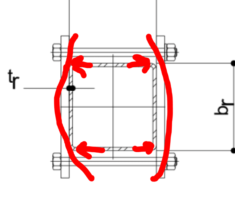
One thing that plays in your favor a bit, I think, is that the plate deformation should focus the clamping reaction right where you want it: over the HSS webs (sketch below). Granted, the tube radii mess with this some.

With regard to thermal swings:

1) Maybe use a twist off nut to ensure a somewhat predictable initial bolt tension and elongation.

2) Do some mathing on the bolt relaxation that you can expect from the thermal swings and what that will mean for your reliable bolt tension.

c01_nlcbiv.png


c02_nrklb7.png
 
You could discuss using Sikadur 30 with Sika. Not quite exactly the application, but maybe they have done before if your load is not unreasonably large.
 
Thanks Koot... I was thinking of stiff clamp plates with holes for PAF, if needed. The thick plates are to minimise deflection. I think torque to determine bolt tension and maybe squish washers... still a work in progress. I was thinking of a COF of 0.2 to 0.25, but am still digging up info. I'm leaning towards small diameter bolts with bottom chamfers. It's looking pretty good and am more confident than I was yesterday.

Brad... I thought about adhesives... I like glue but want to look at clamping. The clamping pressures would likely 'starve' the glue joint.

I'm digging up info on the collapse of HSS walls, right now. Does anyone have any good info on this? Currently using the AISC and STI info...

Thanks Gentlemen...

-----*****-----
So strange to see the singularity approaching while the entire planet is rapidly turning into a hellscape. -John Coates

-Dik
 
You may want a process of how they torque the bolts to make sure they are done evenly..maybe starting hand tight and then a torque pattern going up in intervals.

do they make double sized sandpaper you can put between this connection? [thumbsup]
 
Thanks... I was more concerned about the initial problem, but have come to grips with it can be done. I hadn't thought about tightening, but will include this in the procedure. Again, thanks.

-----*****-----
So strange to see the singularity approaching while the entire planet is rapidly turning into a hellscape. -John Coates

-Dik
 
yup...

-----*****-----
So strange to see the singularity approaching while the entire planet is rapidly turning into a hellscape. -John Coates

-Dik
 
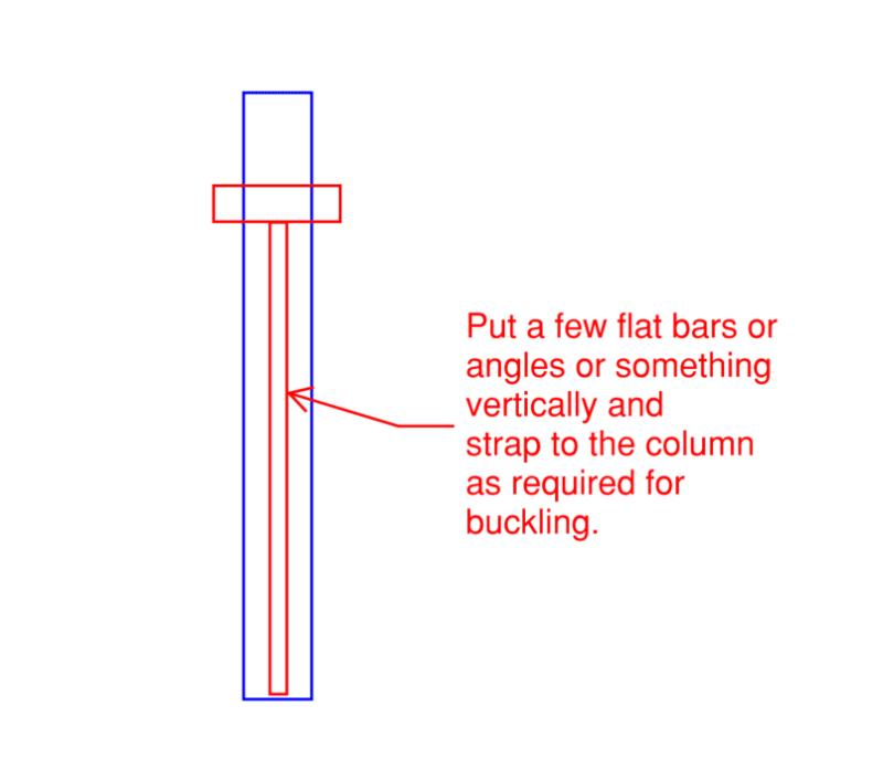
Where is this located vertically? If it's a few feet from the top or bottom could you cheaply create a secondary (or primary) vertical load path? maybe something like this? Basically, run a few baby columns for your item and strap it to the main column for lateral support. If it's close to the top you could just throw a couple of hanger rods in and call it a day.

dik_gqurzw.png
 
Status
Not open for further replies.

Part and Inventory Search

Sponsor