ghylander
Marine/Ocean
- Jun 5, 2023
- 11
I have some pressure data coming from a CFD analysis.
After reading through the multiple posts here and watching videos on youtube, I was able to mostly apply the pressures to my model in a coherent way.
I'm having trouble regarding a specific area of the structure, however.
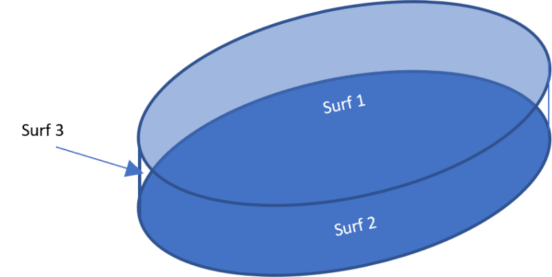
In the CFD software, this area is modeled as a top and bottom surface, with a third surface closing the top and bottom surfaces.
In FEMAP, the area is modeled as a single surface.
What is the corect way to apply these pressures from the CFD to the FEMAP model?
This is my current approach:
The third surface pressures are negligible, so I discard them.
I translate the pressure on the CFD bottom surface to the top surface, by changing the coordinates appropiately.
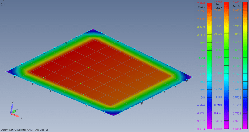
I create a data surface for the pressures on the top surface, and a second data surface for the pressures on the bottom surface.
I create 2 loads, on element, and apply a pressure using each data surface, applied to the front or back face of the elements, accordingly.
Is this procedure correct?
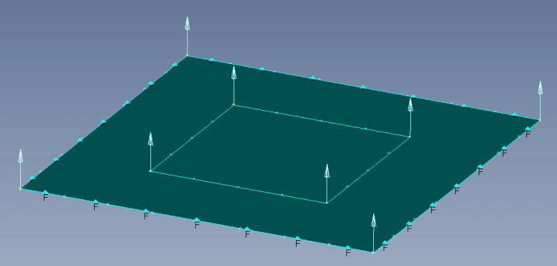
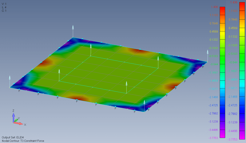
When I toggle loads vector visualization, the vectors for each load (front/back face) are applied on the same side of the surface. Is this just standard FEMAP behaviour (ie nothing I can do will make each load to be visually applied on their corresponding side)?
Is there any way to achive this using a load defined on a surface instead?
Defining the load on the surface, would swapping the magnitude direction (+/-) achieve this?

