Continue to Site

Eng-Tips is the largest engineering community on the Internet

Intelligent Work Forums for Engineering Professionals

  • Congratulations KootK on being selected by the Eng-Tips community for having the most helpful posts in the forums last week. Way to Go!

Data surface pressures on either side of surface

Status
Not open for further replies.

ghylander

Marine/Ocean
Jun 5, 2023
7
I have some pressure data coming from a CFD analysis.
After reading through the multiple posts here and watching videos on youtube, I was able to mostly apply the pressures to my model in a coherent way.

I'm having trouble regarding a specific area of the structure, however.
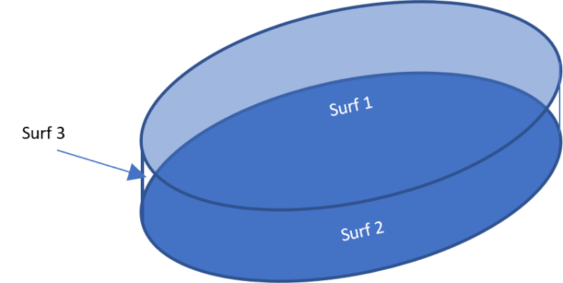
In the CFD software, this area is modeled as a top and bottom surface, with a third surface closing the top and bottom surfaces.

In FEMAP, the area is modeled as a single surface.

What is the corect way to apply these pressures from the CFD to the FEMAP model?

This is my current approach:
The third surface pressures are negligible, so I discard them.
I translate the pressure on the CFD bottom surface to the top surface, by changing the coordinates appropiately.
I create a data surface for the pressures on the top surface, and a second data surface for the pressures on the bottom surface.
I create 2 loads, on element, and apply a pressure using each data surface, applied to the front or back face of the elements, accordingly.

Is this procedure correct?
When I toggle loads vector visualization, the vectors for each load (front/back face) are applied on the same side of the surface. Is this just standard FEMAP behaviour (ie nothing I can do will make each load to be visually applied on their corresponding side)?

Is there any way to achive this using a load defined on a surface instead?
Defining the load on the surface, would swapping the magnitude direction (+/-) achieve this?
 
Replies continue below

Recommended for you

Hello ghylander.
Can you draw simple scheme in Paint to show where is third surface. I think that I understand your setup but it is better to clarify it.

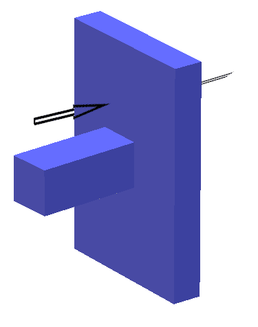
If I recall correct than your problem is like billboard under wind load. There is wind side with pressure greater than atmospheric and opposite side with pressure less than atmospheric. Than your approach is correct. According to superposition principle does not matter if you apply two separate pressures on single element or one resultant pressure, if you use PLATE elements, off course.

If you have surface with attached plate mesh than you can apply load to surface if you want. In this case instead selection positive and negative element sides you can use positive and negative load coefficient.

As for load representation try to use command Model->Load->Expand. This will expand variable load to individual mesh element. Variable loads applied to geometry look weird.

I highly recommend to start with simple model, it can save you a lot of time. Create 2x2 plate elements model. Clamp it on edges and apply two constant pressures to the top and bottom sides, using data surfaces. You can check reaction force, it should be equal to resultant pressure*area. If this works than it should work on full model.
 
Hi karachun

Thanks for the post. I think the case of a billboard under wind load sounds like a fitting aproximation.
This is a quick sketch:

Picture1_gfmsps.png


You can visualize it as a CD, where the 3rd surface woul be the edge itself.

I will try the simplified test, hadn't thought of that.
Fingers crossed about defining the load on surface and swap magnitude sign, I intend to write a macro and that would greatly simplify the complexity.
 
I did the tests you proposed, and I got some wild results.
I performed a total of 4 different tests:
1- Apply load on elements, each pressure on a different data surface, selecting face 1 or 2
2- Apply load on elements, using a data surface summing the pressures on each face
3- Apply a load on surface, swapping the magnitude direction for each face pressure
4- Apply load on surface, applying the summed pressures data surface

Only tests 2 and 4 yield the same results.
Test 1 does not yield the same results as any of tests 2, 3 or 4.
Test 2 yields the same results as test 4 but different to test 1 & 3
Test 3 does not yield the same results as any of tests 1, 2, or 4.
Test 4 yields the same results as test 2 but different to test 1 & 3.

Test 2 & 4 results are approximately 10x the magnitude of test 1.
Test 3 results are completely different from the rest.

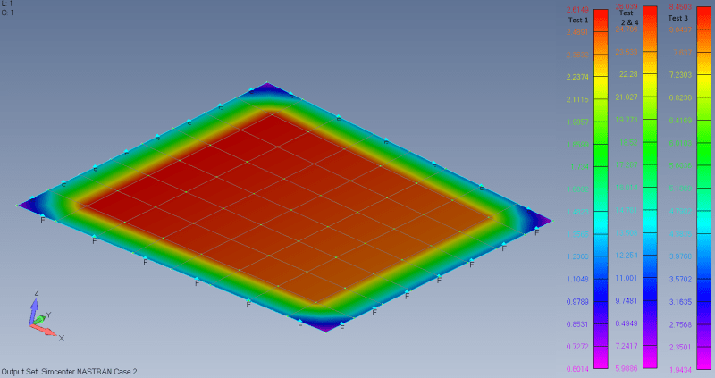
Here are some results, 1 pic of contour on plate and 4 of scales for each test:

Total applied force:
Picture1_wpfe7y.png


Don't know what to think know. Perhaps element front/back face seems intuitively more appropiate?
 
And what results are right and what are wrong? Compare node constraint forces (sum of forces) with calculated reactions.
 
After checking the applied force vs reactions, I actually realised I made a mistake when inputting the data surface with the summed pressures, I entered 9.5e-4 instead of 9.5e-5.
I corrected the issue and re-run the tests, and now all 4 methods check out correctly.

While this was a great find, I realised there may be an additional issue and that I have to run a new test.
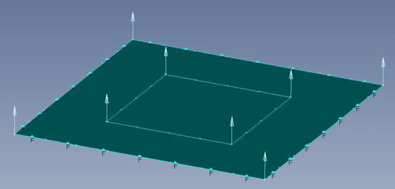
These tests and approaches assume each side of the surface is applied the pressure as a whole, while in reality what I have is:

Screenshot_4_rxnoa7.png


So, on one side of the surface, the pressure is applied to it whole, while on the other side the pressure is applied only on the outer area.
Will test and report findings.
 
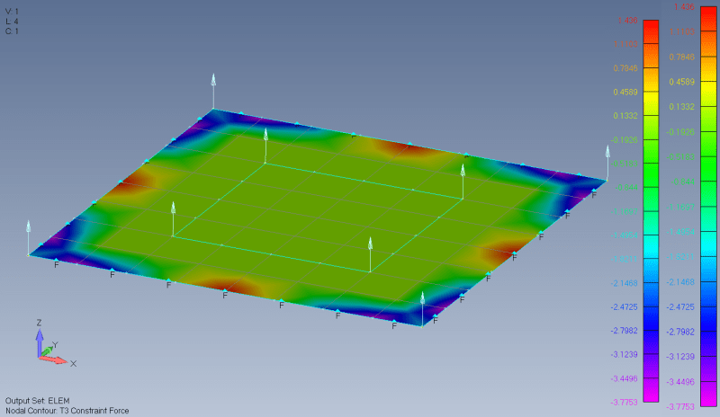
After runnin similar tests for the followig geometry:
Screenshot_1_swktcm.png


The results are similar to the previous tests.
The drawback is that the pressures cannot be easily summed together.
Because of the interpolation, different mesh geometry between CFD and FEM, and different CFD mesh for each surface, you'd have to be very careful when summing the pressures into a single data surface.

It's simpler to just keep a separate data surface and apply it either on geometry or mesh.

Here are the constraint forces contour plot (summing nodal constraint forces match the expected reaction forces for the applied pressures)

Picture1_iwlg18.png
 
"The drawback is that the pressures cannot be easily summed together." ... really ? p*A = force or look at the OLOAD table.

"Hoffen wir mal, dass alles gut geht !"
General Paulus, Nov 1942, outside Stalingrad after the launch of Operation Uranus.
 
Of course they can be summed 'easily'.

I mean that, because one side of the surface is loaded in all its area, while the other side is only being partially loaded, care must be taken with the data surface interpolation.

If the CFD and FEM meshes are very different, it could lead to interpolation using data surface points that do not correspond.

Don't you agree? Am I overlooking something?
 
I guess I misunderstood your "summing" reference.

FeMap has tools for mapping over different meshes, Blais (one of the followers of this forum)is the expert on all things FeMap.

I'd apply your two surface loads as different loadcases, and apply both in the run.

"Hoffen wir mal, dass alles gut geht !"
General Paulus, Nov 1942, outside Stalingrad after the launch of Operation Uranus.
 
Status
Not open for further replies.

Part and Inventory Search

Sponsor