Continue to Site

Eng-Tips is the largest engineering community on the Internet

Intelligent Work Forums for Engineering Professionals

  • Congratulations KootK on being selected by the Eng-Tips community for having the most helpful posts in the forums last week. Way to Go!

Best way to indicate simultaneous profile requirements for a group of features on sheet metal. 2

Status
Not open for further replies.

Ryan6338

Mechanical
Jun 13, 2023
45
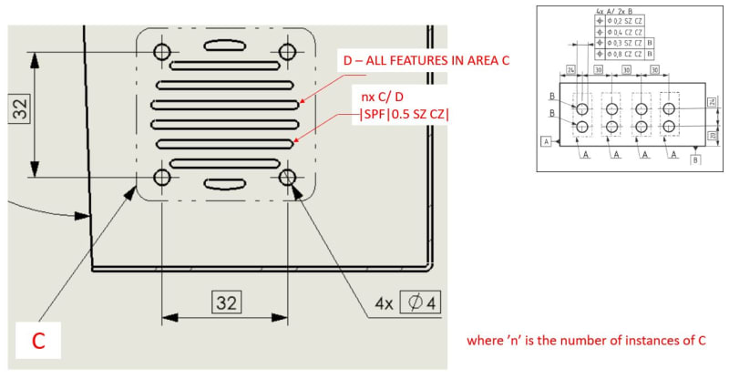
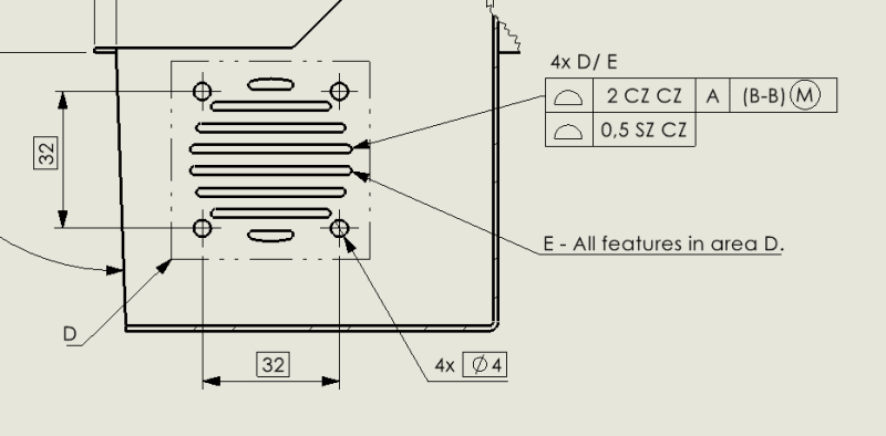
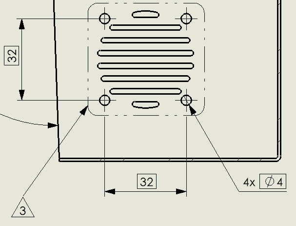
I would like to constrain profiles on particular portions of a folded sheet metal part simultaneously. Is the approach in the images below reasonable when using ISO GPS? Several similar areas are defined throughout the drawing and the same flag note is called out for them. A 3D file is provided with the drawing to specify the dimensions that aren't shown. The intent of this approach is to have tighter tolerances on faces of the sheet metal while relaxing the tolerances around bends. Is there a better way to indicate these requirements?

Capture_fkxvff.png


Capture2_a7o8qu.png


Capture4_dpdwft.png
 
Replies continue below

Recommended for you

Ryan6338,
Your proposal makes sense to me with one or two caveats:

1. Since the secondary datum B-B specified in the general profile callout is defined at MMR (i.e., the datum system does not fully immobilize the part; so called datum feature shift is possible) and because of the default independency principle in ISO, I would recommend to you asking yourself if from functional point of view it is OK that the tolerance zones for all the features controlled by the general profile may be evaluated independently during inspection of the workpiece. If it is not, then I would suggest addition of CZ modifier after the tolerance value of 2 in the tolerance indicator to group all the tolerance zones together.

2. Theoretically, the CZ in the profile tolerance in the note and the word "simultaneously" mean the same thing. I think the note could just say: "In addition to the general profile tolerance, |SPF|0.5 CZ| applies to all features within each specified area, but not across separate areas."

In case you want to try to have the same set of requirements specified in a more symbolic way, you could do something like this (it is sort of inspired by Figure 9 in ISO 5458:2018 which I added to my picture for reference):

profile_pattern_of_patterns_isbfkl.jpg
 
Ryan6338,

One more thing to add regarding the symbolic option:
There would still have to be a note associated with the SZ CZ profile callout stating that the requirement applies in addition to the general profile, otherwise, per the rules of ISO 22081, the general profile would not apply to the considered features.
 
Why SIM does not work in the general profile outside of the tolerance indicator?
 
Thanks for the feedback pmarc. I hadn't considered datum shift in the general tolerance so I will evaluate whether CZ is required there. I like your suggestion of the symbolic representation. Annoyingly I don't think SOLIDWORKS allows multiple indications of CZ and/or SZ in a tolerance frame since they've recently reworked geometric tolerances in drawings. Going the symbolic route I think I'd just stack a profile tolerance on that is the same as the general tolerance rather than putting it in a note.

The reason I used CZ and simultaneously in the note was because I wanted to remove ambiguity as to whether the CZ only applied to each closed profile independently or to all profiles with the area. That said, I think the symbolic method you mentioned resolves any ambiguity issues.
 
greenimi said:
Why SIM does not work in the general profile outside of the tolerance indicator?


pmarc,

And one additional question in top of my initial one:
Why you are not using all around symbol for the profile callout in your latest posted proposal?
And if, all around symbol should be used, then collection plane must also be used? For some "unkown" reason I was under the impression that collection plane callout is tight to the all around profile.
How wrong am I in this issue?

Thanks again
 
Ryan6338,
Glad I could help.

greenimi,
1. SIM REQT is used when multiple tolerance indicators are specified. In the discussed example, there is only one general tolerance indicator, therefore CZ is the tool to use.

2. I did not have to use all around because in my proposal 'D - ALL FEATURES IN AREA C' applies to 36 surfaces and not to 12 features (4 round holes and 8 compound holes).
 
Final result to wrap it up. Had to use tables to enable the use of multiple CZ and SZ callouts, but it looks ok.

Capture5_iogsrg.png
 
pmarc said:
greenimi,
1. SIM REQT is used when multiple tolerance indicators are specified. In the discussed example, there is only one general tolerance indicator, therefore CZ is the tool to use.

2. I did not have to use all around because in my proposal 'D - ALL FEATURES IN AREA C' applies to 36 surfaces and not to 12 features (4 round holes and 8 compound holes).

pmarc,
Thank you for your answer.

Just a challenge and a learning opportunity for me: I see that your proposed solution is not MBD friendly, meaning it is not machine readable as contains a note (“ALL FEATURES IN AREA D”).
How would you convert the same concept to a fully ISO GPS concept which would be MBD gear oriented/ not only human readable.?
I am thinking how to interpret paragraph 9.1.2 from ISO1101:2017
9.1.2 All around and all over — Continuous, closed tolerance feature
If a geometrical specification is applied to the outlines of the cross-sections or if it is applied to all features represented by a closed outline, it shall be indicated by the symbol “all around” placed on the intersection of the leader line and the reference line of the tolerance indicator (see examples Figure 51 and 53). A collection plane indicator shall be used to identify the collection plane in 3D and is preferred in 2D.

I know the OP questions have been answered to a satisfactory level, but I would like to push the envelope a little further for my own edification and improvement in this GPS language.
Sorry for the extra questions, but GPS is not my mother tongue[hourglass][tongue], but I will try to make it with your help and input.

 
greenimi,
I am not sure why you are saying the proposed solution is not fully ISO GPS concept. Because I haven't used the all-around symbol? Again, there is nothing wrong with treating all 36 surfaces in the specified area as individual features which are then are grouped by the CZ modifier in the smaller profile tolerance indicator. The note could have as well said 'D - ALL 36 SURFACES IN AREA C' and the '4x A/ B' could have been replaced with '4x A/ 36x B'.

I deliberately stayed away from the all-around because this would make the drawing look much more complex.

As far as MBD goes, I am not sure the note is a problem from CMM consumption point of view. The proper association of objects would have to be done in CAD software anyway. The note is just a human readable information.

 
pmarc said:
I deliberately stayed away from the all-around because this would make the drawing look much more complex.

So, if ISO GPS offers an "English free" solution (based on symbology only) then I don't see why we should stick with the note option just for the sake of simplicity.
Hmm, Am I missing something and you are really avocating/pushing for simplicity instead of education (which I am trying to get from this discussion)?


greenimi,
Sometimes it is better to take the simplicity route. Especially in the ISO GPS world.

The example from ISO 5458 that I used as reference illustrates pretty simple geometry where there are only two holes within each group, the holes are of the same nominal size and are just single surfaces. That's quite easy to describe with just two labels B and then by applying the rules for multi-level group controls defined in the standard

But the OP case is more complex and we could both easily imagine even more complex scenarios where the conventions used in the standard couldn't be that conveniently applied. This is where a doze of imagination is needed to simplify the drawing that otherwise would be semantically correct but look extremely busy and hard to comprehend.

That's also one of the reasons why I merely suggested to Ryan6338 considering the symbolic way instead of pushing hard for it - I think his original proposal, although utilizing a note, was quite straightforward.
 
So many of these problems would go away if everyone was fluent in Esperanto, but no one wants to be educated. They like the simplicity of the language they have used all their lives over spending hours trying to find out how someone else decided a certain concept should be encoded.

For my own needs I prefer the set operators as exposed in APL. If one needs a cheat sheet - here it is:
As far as I know APL precedes Y14.5 and should have been the basis for all the symbols, like the APL depth symbol ≡.

Only the uneducated would fail to know what "C[;;]←0 ⋄ C" means, when it is so obvious.
 
greenimi, I'm not sure the argument is simplicity vs education. I think it's more simplicity vs strict compliance to the drafting standard. If I were to represent the specification in a fully compliant manner, there would be many more symbols which seems to me like it would increase the chance of any one particular symbol being missed. I believe reducing the symbols - as has been done here - increases readability overall and is a worthwhile trade-off from strict compliance to the standard in my particular situation.

Ryan.
 
OP said:
I'm not sure the argument is simplicity vs education. I think it's more simplicity vs strict compliance to the drafting standard. If I were to represent the specification in a fully compliant manner, there would be many more symbols which seems to me like it would increase the chance of any one particular symbol being missed. I believe reducing the symbols - as has been done here - increases readability overall and is a worthwhile trade-off from strict compliance to the standard in my particular situation.


No disagreement with that.
However, my point was (and still is) how the strict compliance to the ISO GPS / drafting standard would look like ? That's all I was asking all around. It is for my own education and you (the OP) don't have to follow thru on you drawing.

 
greenimi,

I don't think the solution I proposed is noncompliant to ISO GPS standards. There is no need to apply the all-around symbol here. All surfaces within the specified areas may be treated as individual features.

If Ryan6338 wishes, he may replace ALL with 36x in the local note for E and add 36x to the 4x D/E above the stacked profile callouts. This will look even more similar to the example from the standard.

 
pmarc,

You know me as a stuburn individual therefore, I would like to understand how would you interpret 9.1.2 paragraph mentioned above
"If a geometrical specification is applied to the outlines of the cross-sections or if it is applied to all features represented by a closed outline, it shall be indicated by the symbol “all around” placed on the intersection of the leader line and the reference line of the tolerance indicator (see examples Figure 51 and 53)."

In my opinion, the word "shall" is a powerfull word so, I would like to know why the paragraph is not applicable here?
Are you saying that is a difference between outside contours versus inside contours regarding the method of correct applicablility of the all around symbol and also about the collection plane indicators?
I realize this is a compound question, but again, I am trying to educate per the correct usage of the language.

 
greenimi,
The paragraph does not address the situation we are having here. Here, the profile callouts apply to multiple surfaces of which just some form closed contours. There is no need to explicitly group the surfaces into all-around contours.
 
Status
Not open for further replies.

Part and Inventory Search

Sponsor