Eng-Tips is the largest engineering community on the Internet

Intelligent Work Forums for Engineering Professionals

  • Congratulations waross on being selected by the Eng-Tips community for having the most helpful posts in the forums last week. Way to Go!

HSS T Connection at the End 7

Status
Not open for further replies.

dik

Structural
Apr 13, 2001
25,568
CA
Can anyone suggest a good design example for a T connection at the end of a HSS (chord, or column)? similar to the attached. I'm doing up an SMath program to accommodate it.

Clipboard01_qca0r0.png


-----*****-----
So strange to see the singularity approaching while the entire planet is rapidly turning into a hellscape. -John Coates

-Dik
 
Replies continue below

Recommended for you

Dik, AISC Design Guide 24 "Hollow Structural
Section Connections" may be helpful, although I haven't gone through it in a while and don't know if its directly applicable to your situation.
 
I've got it, but it doesn't seem to deal with the end condition very well, unless I'm missing something... also using the CIDECT Guide #3, 2nd Edition... also very good.

-----*****-----
So strange to see the singularity approaching while the entire planet is rapidly turning into a hellscape. -John Coates

-Dik
 
Likely field connections (welded) with temporary bolts. The magnitude is likely in the order of about half the section capacity. Even for straightforward HSS design, I generally don't utilise the section more than about 70%, else connections get pretty messy. The info is for writing a program to check the sums.

Thanks

-----*****-----
So strange to see the singularity approaching while the entire planet is rapidly turning into a hellscape. -John Coates

-Dik
 
Sorry for the repeated follow-ups. What's the plan for holding the beam in place during erection? Can Pf and Mf reverse directions?
 
Possibly a little clip bearing angle. As a program, I'll accommodate all direction of forces.

-----*****-----
So strange to see the singularity approaching while the entire planet is rapidly turning into a hellscape. -John Coates

-Dik
 
I'm not aware of any examples addressing this specific scenario.
I think its safe to say that without a cap plate, your moment capacity would be somewhat reduced compared to if it was in the middle of the column. With a cap plate as shown (that is sufficiently attached to the top of the column) I would guess that it would be the same as or even somewhat conservatives to treat it as if it were in the middle of the column.
 
Thanks dauwerda... my thoughts, too. I was just hoping that I could formulate the strength. I've already done a regular T connection and wanted to extend it. CIDECT DG 3 is excellent, BTW.

-----*****-----
So strange to see the singularity approaching while the entire planet is rapidly turning into a hellscape. -John Coates

-Dik
 
This is an Australian design guide but I've found it quite comprehensive:

I might even be able to provide the suitable pages if required.


IMO that T joint could be designed better. It is difficult to get the required fillet welds in the areas nominated due to the radius of the HSS. The way I do these joints is as a mitred joint with aa plate in the middle. There is research showing the performance of these joints being superior to alternatives. Also suitable fillet weld size can be achieved much more easily than butt welded mitres or a T with fillets.
Figure-1_bwdttc.png

 
Thanks human... I have information for mitred corners and reinforced mitred corners... I was looking for something that does 'a beam and column' type of connection.

-----*****-----
So strange to see the singularity approaching while the entire planet is rapidly turning into a hellscape. -John Coates

-Dik
 
271828 said:
. What's the plan for holding the beam in place during erection?

I would let the erector figure that out. That has never been an issue on any of my jobs.
Is that some sort of OSHA requirement?
 
XR250 said:
I would let the erector figure that out. That has never been an issue on any of my jobs.
Is that some sort of OSHA requirement?

I typically work for the fabricator and I think dik does also. We need to provide a connection that won't be a pain to deal with.
 
dik:

I have never seen an example for this. I have run into it a few times but don't have an example that's anywhere near clean enough to share. Some thoughts follow. Hopefully they'll be helpful.

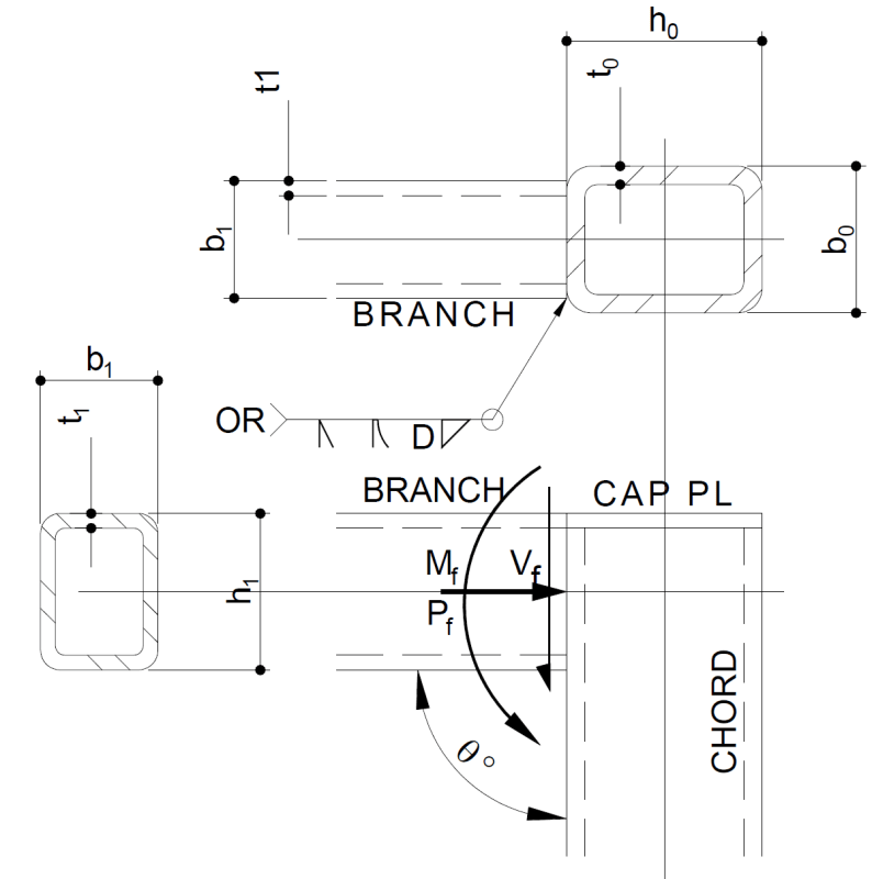
Assume the beam axial load is shared by all four walls on the basis of their areas. Assume the shear goes through the two vertical walls and the moment is resisted by a force couple between the top and bottom walls.

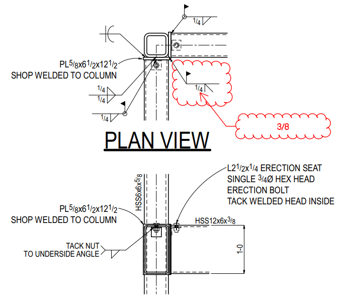
I typically make the cap plate wider than the column so it can be connected with fillet welds. The cap plate is usually overly thick to allow sufficient shelf dimension for the top wall-to-cap plate fillet weld.

Most of the checks are pretty vanilla, so I won't list them and bore you to death. Every time I've seen this, one of two things controls:

Column wall out-of-plane bending, aka plastification. I check this with the AISC Manual (15th ed.) Figure 9-5(a) and Eq. 9-30. Sometimes this controls by quite a bit, leading to through-plates like shown in DG24 Figure 4-4.

Weld strength at the beam bottom wall. Effective weld length from the AISC Spec. Eq. K1-1. That's a pretty short length sometimes, so it's often hard to make fillet welds work. Might need a CJP with backing instead -- then check the beam bottom wall for tensile yielding on that little effective length.

More thoughts:

Some checks are shown in the AISC DG24 Example 4.3.

The following also applies to the column wall strength at the beambottom flange: Web Local Yielding and Web Local Crippling from the AISC Spec. Sections J10.2 and J10.3, respectively. If there was another beam on the right in your figure then Web Compression Buckling from Section J10.5 would apply. Finally, don't forget Web Panel-Zone Shear from J10.6.

 
Thanks 271... that was the approach I was going to follow... but was going to include the 'webs' in the flexural calcs (I have an SMath program written for weld stresses). Only concern was the wall plastification and the weld stress distribution across the face HSS width. I've almost exhausted myself looking for a good example... maybe there are not any. Will do it the 'long way'. Thanks everyone.

Take a gander at the CIDECT DG 3, 2nd Edition... it's excellent.

SMath output, but for a different problem...

Clipboard01_r9yjcz.png


-----*****-----
So strange to see the singularity approaching while the entire planet is rapidly turning into a hellscape. -John Coates

-Dik
 
We use end plates pretty frequently to circumvent the tiny workable flats on some of the thicker-walled HSS sections and provide a substantial flare bevel weld to the column. I thought this erection seat inside the HSS section was pretty clever, but this was for a relatively lightly-loaded stair tower moment connection.

aaa_a0zev8.png
 
Erection seat and temp bolt is great... borrowed... thanks.

-----*****-----
So strange to see the singularity approaching while the entire planet is rapidly turning into a hellscape. -John Coates

-Dik
 
Dik can you post the CIDECT guide. The website says its no longer available for download.
 
Dik

These references might be of some use.

Steel Tube Institute
RECTANGULAR HSS CONNECTIONS CLOSE TO A CHORD END
by Jeffrey A. Packer
Bahen/Tanenbaum Professor of Civil
Engineering, University of Toronto,
Ontario, Canada

RHS-to-RHS axially loaded X-connections near an open chord enc
by Fan and Packer
Canadian Journal of Civil Engineering
Vol 44, Issue 11
 
Status
Not open for further replies.

Part and Inventory Search

Sponsor

Back
Top