Eng-Tips is the largest engineering community on the Internet

Intelligent Work Forums for Engineering Professionals

  • Congratulations waross on being selected by the Tek-Tips community for having the most helpful posts in the forums last week. Way to Go!

Air Intake during Drainage 1

Status
Not open for further replies.

Jack.C

Industrial
Feb 17, 2023
12
0
0
CH
Dear All,

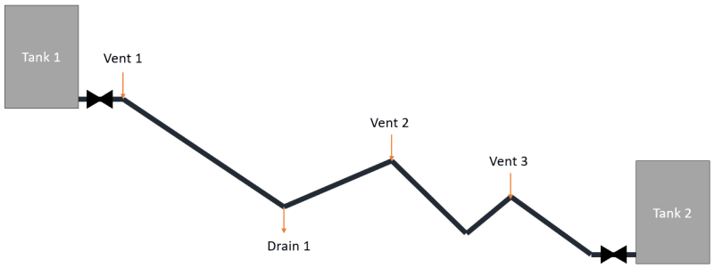
I am reaching out once again with a question and would greatly appreciate your valuable insights, as you have consistently provided in the past. Kindly refer to the accompanying sketch for context.

Situation:
I am currently dealing with an isolated pipeline that is being emptied via Drain 1. The pipeline is equipped with 3 vents, all of which are in the open position. The maximum drainage rate achievable is 300 m3/h. Consequently, it is imperative to ensure an equal airflow into the pipeline to prevent the occurrence of under-pressure.

Initial Consideration:
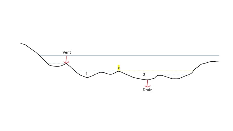
My initial contemplation led me to allocate a vent capacity of 100 m3/h to each of the three vents (Vent 1, Vent 2, and Vent 3). However, upon closer examination, Vent 3 appears to have no contribution due to its lower positioning. Consequently, it appears necessary to appropriately design Vent 1 and Vent 2, both with a capacity of 150 m3/h each.

Query:
In an effort to streamline my evaluation process, considering the numerous drains and vents involved along the pipline, I need you advice on the potential impacts of adopting the following approach when calculating vent capacity for air intake:

Q_intake = Q_max_drainage / n

where "n" represents the total number of drains. Applying this formula to the aforementioned scenario, would the resulting air intake capacity (for Vent 1, Vent 2, and Vent 3) indeed be 100 m3/h (?)

Clarification:
Imagine if the drainage process were to pull water from the lower section of the pipeline (since the air intake of Vent 1 and Vent 2 are only 200 m3/h together. Would this potentially activate Vent 3 at some point, especially if the capacities of Vent 1 and Vent 2 are insufficient? Or is it more likely that the drainage flow would just stay limited to a total of 200 m3/h without any significant problems / damage to the pipeline (steel pipe)?

Thank you in advance for your inputs!

Cheers,
Jack

sketch_welvcj.png
 
Replies continue below

Recommended for you

Vents, or air entry valves?

No. Do not try to size using Q/n. Treat each segment independently.
Proceed with the assumptions that Drain 1 will only drain the segments between vent 1 and 2.
Tank 2 will drain segments between vent 2 and 3 and tank 2, until water level reaches the level of vent 3. Therefore drain from vent 2 to 3 into tank 2. It may or may not be possible to drain the "V" below vent 3 elevation between 2 and 3 by siphon action, depending on the drain rate to tank 2.

Drain rate can be controlled by outlet valves at the drain 1 and through the valve at tank 2 to keep up with air entry rate. That maximum may be determined by size of valves and/or maximum head on those valves at any given time.

All you have to do is keep the air entry rate into each segment >= drain rate out from the drain points. They probably does not need to be drained at the maximum gravitational flow rate. Do not drain faster than air can enter and no vacuum will form anywhere. That means controlling the drain rates to always be less than air entry rate.

If you drain all segments at the same time through drain 1 and tank 2, size air entry at vent 2 for the sum of the drain rates at drain 1 and at the tank. Vent 3 could conceivably be less, at just the drain rate of the last segment into tank 2.

I would first drain Tk1 to vent 2 to drain 1. Only then open valve to tank 2.

--Einstein gave the same test to students every year. When asked why he would do something like that, "Because the answers had changed."
 
Can you advise what the levels are of the high points and low points. Also distances and pipe sizes?

Remember - More details = better answers
Also: If you get a response it's polite to respond to it.
 
Not knowing much about your system such as pipe diameters, lengths, drain and vent sizes, elevations, etc., I have the following comments:

Your drain rate appears way high at 300 m3/hr (1320 GPM) what is your drain size 6" or 8"? Seems like drainage rate is too large and can drain the pipeline in a couple of minutes or so. Why not smaller drainage rate and hence smaller drain and vents.

Not knowing the pipeline diameter, it seems like there would be no problem with drawing somewhat negative pressure to get the proper air vent flowrate into the pipe. I designed piping systems for most of my career and all we used were standard vents and drains per client details or on larger drain lines sometimes for quicker drainage rates may 2" or even 3" drains but never calculated flowrate of air into pipe and corresponding pressure drop across vent pipe to determine resulting pressure in pipe. Any decent size vent would give a good flowrate at even inches w.g delta P or even 1 or 2 psi delta P. Can this really collapse a small diameter pipe? ASME has calculations for collapsing of pressure vessels you can check with those equations.

If you open drain and vents at same time flow will come out of vents 2 and 3 until the water level in the first pipe segment drops. If you just open vent 1 and 2 and drain then liquid will come out of vent 2 for a while until the level drops in the first segment. In this case would not the drainage rate be even greater and with only vent 1 allowing makeup air into the system? I believe you need to come up with an idiot proof drain and vent system so that whatever operators do there would be no negative consequences, unless you develop a drainage procedure that is posted somewhere prominent so that you would be assured it will be followed but even then I would not count on it. Something wrong happens and the first thing they will do is blame you.

I would look at draining everything into the lower tank by just opening vent 1. It may all just all flow by siphon effect but I am not sure. If not lowpoint drains at low spots can drain the remaining liquids. Why just empty the entire pipeline onto the ground making a mess and wasting the liquid. I assume this is water.
 
I don't know where you are getting the capacity of the air vents from?

The actual air flow will depend on size of the event plus the differential pressure from 1 bara to some negative atmospheric pressure. What did you assume?

But I would forget about the "capacity" of the vents - you're going in the wrong direction with that thinking.

I don't know what your issue is with "under pressure"? Can you explain?

If vent 2 high point is < about 8m higher than the low point between vent 2 and 3 then it could syphon some liquid if vent 3 is open.

Same about this seciton oif you drain the pipe into tank 2. leave vent 2 open, drain into tank 2 until no more flow then open vent 3.


Remember - More details = better answers
Also: If you get a response it's polite to respond to it.
 
Dear all.

Thanks a lot for your feedbacks. Really helpful!

@Snickster: My drain rates are even higher than this. I have a DN1200 pipe around 30 km in length. The complete line is divided into two sections. The maximum drain time is given by client. Therefore, we added for each section a larger drain at the lowest point in the profile. That is actually what brought me to this question. If I only have the largest drain open, is it even possible to drain the system like this? Imagine that I have lots highpoints and lowpoints along the profile. As far as possible I try to drain via the tanks connected to this pipeline. But at some point I end up with a static head below the lowest tank inlet. When I then open the larg drain to dispose the water safely in the adjacent river, I will have many syphons.

@LittleInch: We estimate the vent capacity based on the empirical approach published by the engineering monograph 41.
The issue with under pressure (negative atmospheric pressure) is that I don't want to fall below 0.3 bara. To explain my concern, let's add another example with only 1 drain and 1 vent (not a real scenario but to understand the effect):
-> blue solid line = initial head (after draining into the tanks)
-> blue dashed line = ideal final head (after draining over drain)
-> assuming that there is not other air source except this one vent and no other possibility to drain except this one drain.

Question: Is it possible to drain the volume 2 (yellow dashed line)? In other words, does the vent still contribute air into the system despite of the sealing by intermediate highpoint X and the remaining water (volume 1)? Or is the volume 1 sucked out as well at some extent?

sketch2_xcrxxg.jpg


Please have patience with me :) Thanks & have a great day!
 
Jack,

In theory yes it is possible, but depends on the level differences between the high and low points along the route.

If the bottom of 1 to X is more than 9 to 10m then no as there isn't enough pressure to lift the water up the hill, even with 0.1 bara at X and the vent open.

Also once the water column gets to point x then air will start to bypass the water column leaving some water in place.

So even if 1 to x is >10m, some of the water in this section will drain below the level of 1 until the driving force (atmospheric pressure) can't overcome the static head between the water air interface and the net high point downstream.

Remember - More details = better answers
Also: If you get a response it's polite to respond to it.
 
There may be a way, combining siphon and velocity head, if you can drain the yellow section at a velocity high enough to climb the hill 1 to x, but there are siphon velocity limits. It is very sensitive to height difference between 1 and x.

If you really need to drain the line completely, you might alternatively try that by pushing spheres through the whole length of the line with a compressed gas, draining at x until the spheres arrive there, then turning the drain off and pushing whatever water remains to the end of the line.


--Einstein gave the same test to students every year. When asked why he would do something like that, "Because the answers had changed."
 
I don't understand why you have not posted the elevations as well as what is the purpose of this line. Won't draining of the pipeline increase the steel corrosion?
 
Transient flow conditions are always difficult to analyze but I have some concerns based on the most recent hypothetical diagram and question posted about whether the vent to the left will serve to vent to piping to the right of the drain.

In the beginning static equlibrium exists so that the static pressure of the column of liquid to the right of the drain equals the static pressure of the liquid to the left of the drain an so static equilibrium exists. As the left side is drawn down the static pressure head of this side at drain location reduces so that the pressure at the drain will decrease base on the left side. For static equilibrium to exists the right side will also need to reduce in static pressure contribution at drain location. This can only be done by creating a vacuum in the right side water column which eventually will reach vapor pressure of the water as the left side continues to be drawn down. Wasn't this what was trying to be avoided?

When water draws down on the left side of the drain there will be instances where a negative siphon type pressure will be developed due to the column of liquid on the right side of the high point X pulling a vacuum on the liquid to the left side of point X. I can see that a vacuum/negative pressure can be formed on the right side of X causing a negative pressure less that atmospheric pressure that is acting on the fluid on the left side of X so a pressure differential occurs to keep pushing/moving the fluid over the hump at X. However my question is when the fluid encounters a long almost horizontal run on the left side of hump/humps, the air-liquid interface is vertical. In this case there is a static pressure difference between the liquid at the top of the pipe and that at the bottom of the pipe of 4 feet (DN1200 pipe). Will this cause the water at the bottom to flow backwards while air enters at the top which will break the vacuum and cause the pipe to not be drained fully, and just how much water will not make it over the hills? Also appears will also have issue of negative pressures forming in some areas which was what was trying to be avoided.
 
Since the diagram ends on the right, I assume, rightly or wrongly, that there is an outlet there, which can be used to let air into the pipe on the right thus preventing vacuum.

In your scenario, no inlet /outlet on the right, drawdown there will go to vapor pressure, however water from the left will then attempt to cross through the drain junction and enter the right side pipe as it attempts to reach the same level that it has on the left side and heads will always balance and drain equally on each side. But a fast drain rate might prohibit that.

As for horizontal pipe, draining rate should be done fast enough that the water will not have time to flatten out and allow a long horizontal water-air interface to form. If you get some large diameter clear plastic garden hose, you will see that it is possible to do it, if drain velocity is fast enough. But the right side would develop vacuum, if there is no air inlet possible where the diagram ends.

--Einstein gave the same test to students every year. When asked why he would do something like that, "Because the answers had changed."
 
My understanding is that the entire pipeline is first drawn down into the downstream vessel as much as possible, In this case the water head is equalized at the end to be on right to the static height head of the downstream vessel and on the left to the same static equillibrium head. Then block valves at both tanks are close and the pipeline is drained. So the right side is not open to atmosphere but to block valve at shut in pressure before valve was closed, and the line is packed on the right.

Correct - no inlet /outlet on right so drawdown will go to vapor pressure on the right. No - water on the left will not tend to cross the drain junction because the pressure at the drain junction is determined by the static head of the water on the left, and the pressure head on the left and right must add up to be equal to the same static head at the drain. What will happen is that the water on the rigtht static head will always be in equillibrium with the static head of the water on the left.

The horizontal draining rate is only 0.25 feet per second, for 300m m3/hr in 48" diameter pipe, which is almost zero velocity for practical purposes. A large diameter plastic hose is still a small diameter (what 3/4"?) in this case there are intermollecular forces between the molecules in the hose and the molecules of the water to keep the water clinging to the hose and prevent it from flowing backwards - this is the principal of capillary action.
 
That would immediately put an undesired vacuum on the right side, so surely if the intent is to avoid that condition, a vent of some kind on the right is necessary. Least that is what I assumed. I don't know one way or the other.

"What will happen is that the water on the rigtht static head will always be in equillibrium with the static head of the water on the left."
There would be atmospheric pressure on the left pipe surface, but vapor pressure on the right surface, so there could be roughly +600mm difference in elevation on the right side of the 2 water surfaces, after any transients from column separation stabilise. And I can see at least some possibility of back and forth flow happening while the drain flow is establishing itself.

Without going into 2phase slug or bubble flow regimes, sure there is a possibility that a long air-water surface interface could form if high enough velocity is not possible. That would leave water at the low points, or puddles within the pipe. If a complete drainage is needed, spheres or squeege pigs with a gas chaser will probably be needed to push it out.

--Einstein gave the same test to students every year. When asked why he would do something like that, "Because the answers had changed."
 
Status
Not open for further replies.
Back
Top