Hello,
I’m working on the design of an investment casting and have a question regarding interpretation/application of a tolerancing standard to the product. For background, the casting is an investment casting made of CF3 (UNS S30403 Equivalent). Our product definition is IAW ASME Y14.5-2018. We sent out RFQs and one of the vendor’s quotes indicated that the part’s tolerance and surface finish would be IAW VDG P690-2010, Grade D2. VDG P690 references ISO 1101 GPS and I do not have great familiarity with the ISO GPS standards.
I’ve gotten a copy of the VDG standard referenced and am evaluating our design to see whether or not the part would meet our requirements if produced to the tolerances provided by the vendor.
What I’m having some trouble with is the following:
1. Our product definition relies on a profile of a surface to control many surfaces of the part.
2. Our product definition also utilizes several position callouts / tolerances for features of size.
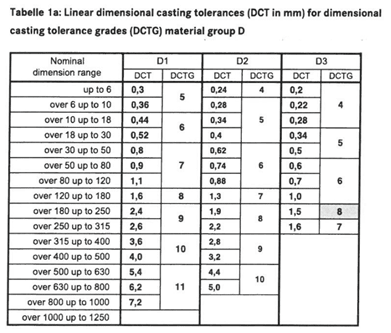
In both cases, VDG-P690 only really provides linear dimensional casting tolerances which, I think, would be used in my evaluation for these features. The linear dimensional casting tolerances are provided in a table and are based on the nominal dimension and the accuracy grade of the casting (1 thru 3).
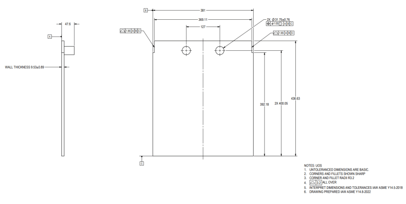
I’ve mocked up a drawing which is representative of my design in both the application of ASME Y14.5-2018 and the size of the product.
Below is the example drawing for discussion, followed by my questions. Please don’t read too deeply into the number of decimal places on the example. I just converted all dimensions to mm to avoid asking anyone to switch units.


A. Looking at the profile of a surface of the two vertical surfaces with basic distance of 369.11 held to PFS 1.65 to ABC. My interpretation is that if measured with calipers, measurements could vary between 369.11 +/- 1.65 based on my definition. In looking at the table from VDG P690, this corresponds to the nominal range of over 315 up to 400 mm. Under grade D2, the tolerance would be 3.2. My understanding is that this is a problem and my drawing is tighter than the standard allows. Is my application of the tolerance from VDG P690 correct?
B. Looking at the circular boss and its size and position, do I apply the VDG P690 linear tolerance to the size of the feature? If so, the standard indicates that the linear tolerance for a nominal dimension over 30 up to 50 is +/- 0.74. Because my drawing calls out +/- .76 on the diameter, my drawing is tighter than the standard allows. Is this correct?
C. Looking at the position tolerance on the boss, do I apply the standard’s linear tolerance to the position of the boss from datum C? In this case, the distance from datum C is 400.05. From the tolerance grade table, a linear dimension over 400 up to 500 has a tolerance of +/- 3.2. My drawing calls for a position tolerance on the boss of Ø1.02 @ LMC. My drawing is tighter than the standard allows. Is this correct?
I just need to know if I’m interpreting and applying the tolerances provided in VDG P690 correctly to my part. I’m certain I can accommodate looser tolerancing, but I just need to verify my understanding.
Thank you.
I’m working on the design of an investment casting and have a question regarding interpretation/application of a tolerancing standard to the product. For background, the casting is an investment casting made of CF3 (UNS S30403 Equivalent). Our product definition is IAW ASME Y14.5-2018. We sent out RFQs and one of the vendor’s quotes indicated that the part’s tolerance and surface finish would be IAW VDG P690-2010, Grade D2. VDG P690 references ISO 1101 GPS and I do not have great familiarity with the ISO GPS standards.
I’ve gotten a copy of the VDG standard referenced and am evaluating our design to see whether or not the part would meet our requirements if produced to the tolerances provided by the vendor.
What I’m having some trouble with is the following:
1. Our product definition relies on a profile of a surface to control many surfaces of the part.
2. Our product definition also utilizes several position callouts / tolerances for features of size.
In both cases, VDG-P690 only really provides linear dimensional casting tolerances which, I think, would be used in my evaluation for these features. The linear dimensional casting tolerances are provided in a table and are based on the nominal dimension and the accuracy grade of the casting (1 thru 3).
I’ve mocked up a drawing which is representative of my design in both the application of ASME Y14.5-2018 and the size of the product.
Below is the example drawing for discussion, followed by my questions. Please don’t read too deeply into the number of decimal places on the example. I just converted all dimensions to mm to avoid asking anyone to switch units.


A. Looking at the profile of a surface of the two vertical surfaces with basic distance of 369.11 held to PFS 1.65 to ABC. My interpretation is that if measured with calipers, measurements could vary between 369.11 +/- 1.65 based on my definition. In looking at the table from VDG P690, this corresponds to the nominal range of over 315 up to 400 mm. Under grade D2, the tolerance would be 3.2. My understanding is that this is a problem and my drawing is tighter than the standard allows. Is my application of the tolerance from VDG P690 correct?
B. Looking at the circular boss and its size and position, do I apply the VDG P690 linear tolerance to the size of the feature? If so, the standard indicates that the linear tolerance for a nominal dimension over 30 up to 50 is +/- 0.74. Because my drawing calls out +/- .76 on the diameter, my drawing is tighter than the standard allows. Is this correct?
C. Looking at the position tolerance on the boss, do I apply the standard’s linear tolerance to the position of the boss from datum C? In this case, the distance from datum C is 400.05. From the tolerance grade table, a linear dimension over 400 up to 500 has a tolerance of +/- 3.2. My drawing calls for a position tolerance on the boss of Ø1.02 @ LMC. My drawing is tighter than the standard allows. Is this correct?
I just need to know if I’m interpreting and applying the tolerances provided in VDG P690 correctly to my part. I’m certain I can accommodate looser tolerancing, but I just need to verify my understanding.
Thank you.
