Continue to Site

Eng-Tips is the largest engineering community on the Internet

Intelligent Work Forums for Engineering Professionals

  • Congratulations waross on being selected by the Eng-Tips community for having the most helpful posts in the forums last week. Way to Go!

Field welding a bolted splice connection 2

Status
Not open for further replies.

a50860

Aerospace
Jan 28, 2012
10
Hello, I need to provide a design to field weld a splice connection between 2 box truss beams that have plated ends. We normally bolt them together, however, the plate hole patterns aren't aligning. I'd like to weld the plates together and was hoping for some feedback on my plan. Any feedback would be greatly appreciated!

geometry:
- box truss beam with plated ends. the beam is split into 3 equal parts with splices at 1/3rds.
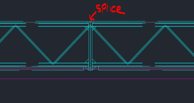
truss_beam_splice_dchhyn.jpg


loading:
- vertical cyclical loading with a known dead weight
- horizontal wind load per ASEC7
- normal loading conditions with the bottom of the beam in tension and top in compression. +/- for the wind plane.

plan:
I'd like to specify SMAW with AWS D1.1-2020 detail BC-P2 since T[sub]1[/sub] allows unlimited depth. however, I don't think I really have a butt weld here, but I can't find a good match for welding edges of plates together. can I consider this a large butt weld and use detail B-P3?

issues:
- D1.1 4.18.1 one-sided groove welds is prohibited for cyclical loading

I'm wondering if anyone knows a better prequalified weld detail to use if I plan to add weld to portions of all sides of my plate connection?

Thanks for taking a look!

--
Mitch
 
Replies continue below

Recommended for you

A better picture/sketch of what you are trying to do would probably help.
Is there a reason holes can't be field drilled to allow for bolting still? I imagine welding would cost a lot more than drilling would.
 
Hi Dauwerda, I try to avoid field welding however in this case we shipped with mixed plate inventory. If I have them drill out to match I'll end up with a slot in the vertical direction. The splice plate is cored out in the center to reduce weight, so I don't have enough room to add new holes.

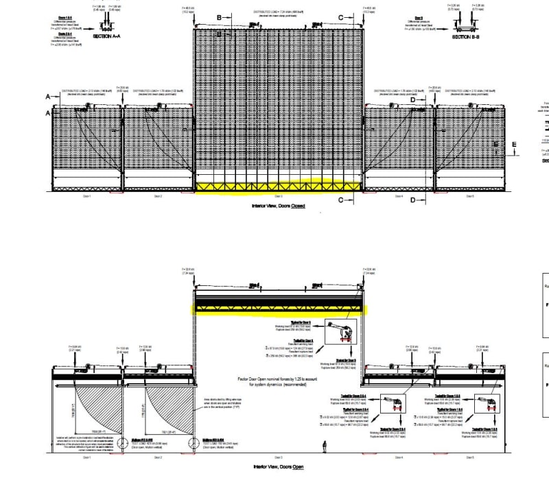
I'll explain more about what we're trying to do. This is a door system and we are having issues with the center door; it's similar to a Venetian blind where you have a bottom beam that gets loaded up with the door package as it opens (hence the cyclical dead weight loading part). It also resists a portion of the wind load when the door is closed. here is the door in the open and closed position with the beam highlighted.

door_open_closed_ornrwj.jpg


I want to add weld to the splice connections to keep the job running. We're not setup to replace plates in the field due to the tolerance requirements for the door system.

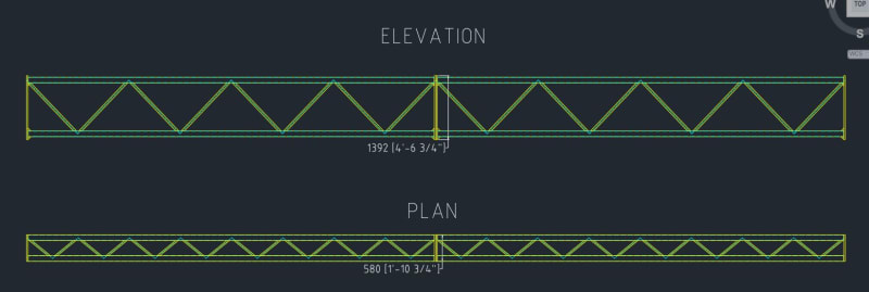
here's the beam in elevation and plan with some dims of the splice

overall_pimtoj.jpg


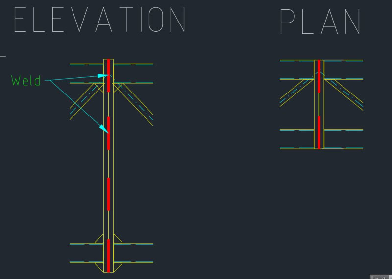
my plan is to add weld to all four sides of the splice something like this:

splice_welds_xjhdzi.jpg


we're more of a mechanical department that has a standard set of calcs and procedures to deal with the structural side of things. I'm decent with AWS D1.1 and ASIC 360 but I just wanted to get an opinion from a structural pro. I figure I'll be asked for a welding plan and likely some calculations on this job so I want to make sure I'm prepped.

Thanks for your help!


--
Mitch
 
Top chord - likely no problem. Cyclic but no load reversal, right?

Your tension-side plate bending is going to control. You can't just CJP weld around the edges. The thing would pry apart.

If you give us more of the geometry we might have more precise advice.
 
Hey JLNJ, thanks for the input.

yeah it's cyclic but no load reversal in the gravity direction. however, we do have load reversal in the wind plane.
we have a good set of calcs and a long history of neutrally sealing our chords, branches, and how we weld the beam.. So, i'm comfortable with the individual beam sections.

That tension side is what I'm really concerned about. wouldn't these be PJP on the edges? also, it would be a lot of work, but If I had them weld continuously all around the exterior and the interior edges of cored out section, would it be considered a built-up shape?

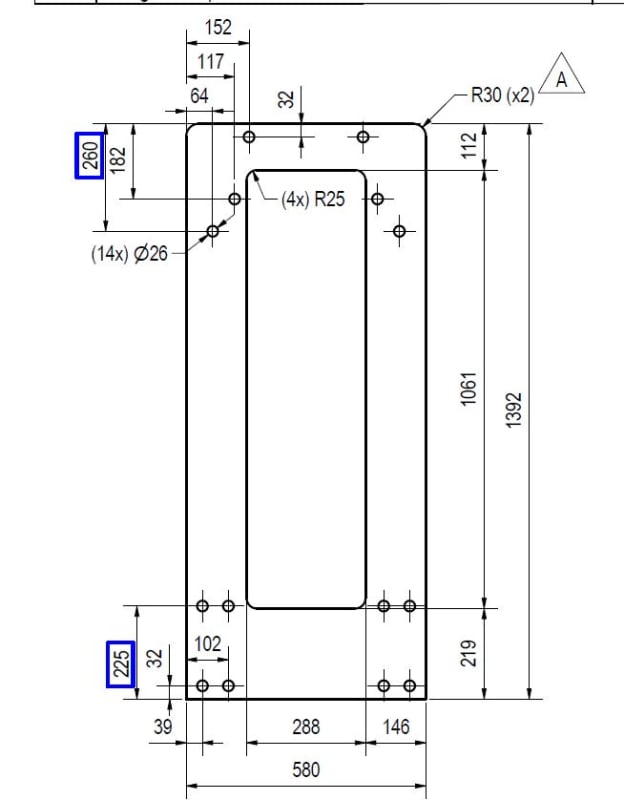
Those splice plates are A572 grade 50, 32mm thick
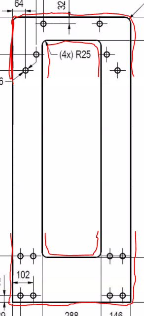
here's the flat file for the splice plate
splice_plate_rdjxta.jpg


appreciate your input

--
Mitch
 
If you could weld the inside and outside, something like the following I might be able to get on board with it:

weld_locations_lmf3tg.png
 
How misaligned are the holes? Can you just oversize the holes and fasteners?
 
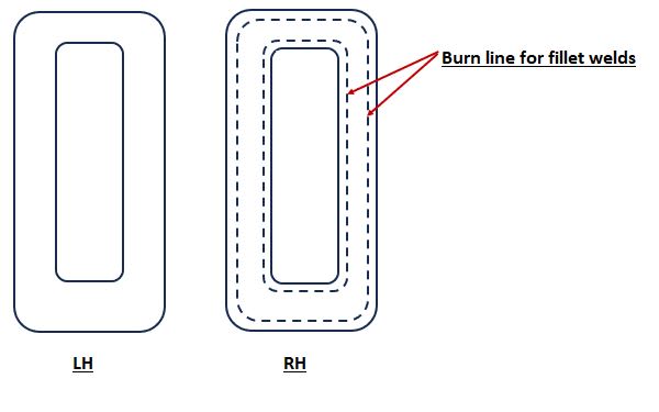
It looks like there might be enough plate to burn 12mm all the way around one side and then get a fillet weld - could burn 12mm off of inside and outside

burn_mucmls.jpg
 
A50860:
Getting real engineering info. out of you guys is like pulling teeth. What you’ve shown so far is interesting in gaining a general understanding of what you’ve got and what you are trying to do. But, to answer your question, we need the actual fab., part details, assembly, and erection drawings which show part sizes, thicknesses, dimensions, existing weld details, etc. etc., around that joint; not more vague CAD drawings which don’t show any detail, sizes or dimensions. What does the intended bolted joint consist of, that may give us some clues as to the original design intent? Someone needs the moment, shear, reaction diagrams on that box beam, forces in the various members, etc. While one function is lifting and supporting the door system, how is that done and how is the box beam loaded and supported, load and reaction diagrams? Is that really a simply supported beam with a uniform load in the vert. direction (gravity)? With the wind loading on that large a door, positive pressure and suction, all four corners of that box beam will see some tensile forces, maybe not enough to put the joint (that corner) into tension, but who knows?

Prequalified weld joints is hardly the biggest of your concerns, those joints have to be designed for the loads and cycling they will see. The two prequalified weld details you selected do look a little like your problem, but are far from it, and you better realize that if you are going to design this new joint and its welds. The AWS/AISC welds are loaded primarily in the plane of the plates being joined, your’s is certainly not. Thus, JLNJ’s comment “The thing would pry apart.” Just because the welded joint is prequalified doesn’t mean you have designed it correctly. It just means that the weld can be relatively easily and practically made, with some degree of certainty of getting a quality weld. If your drawings are to scale, those butt/end plates look to be about 1.5" thk., by 4'-8" high, by 2' wide, and cored, whatever that means. I don’t think this problem is simply replacing a few bolts with some welds. It requires a real study of the load paths through those joints, if you want it to hold up over time. I do think a welded joint is possible, but I need to see the details to confirm this.
 
Thanks for the inputs.

dauwerda, this is really what I'm looking to do. I would specify a PJP groove weld on both sides to limit the plate from buckling and stressing the weld root.

SWComposites, that was the first fix I looked at. The issue with drilling out the holes is that I'll end up with vertical slots. The only fix I can see working is to weld the plates together (other than getting it back to the factory and putting the correct plates on it so we can bolt)

dvd, unfortunately, we have the chords coming in at the edges of the plate. so, we wouldn't be able to burn the edges. I think the only welding option would be to use a PJP groove

dhengr, I appreciate the need for more information. Unfortunately, I can't publish the fabrication drawings for IP & contractual reasons. I guess I'm looking for general code-based objections to making a weld at a box truss splice in a cyclic-loaded beam. My team are mechanical engineers but they are good at sizing members, welds, calculating loads, etc... we just lack the deep code knowledge of a SE for doing things that don't conform to our standard product offering. The beam is simply supported; it's end-picked by a wire rope hoist. It also rides on rails attached to jamb steel to support the wind load. so, simply supported in 2 directions. Those dims I showed are accurate; plates are 32mm thick, 1392mm tall, 580mm wide. The plates are cored in the center out to save on weight per that flat file above. Overall, the beam length is 26778mm (87' - 10 1/4") and it has 3 sections that are 8926 (29'-3 1/2").. so, 2 splice locations at 1/3 locations. It's loaded with 17922kg (39511 lbs) vertically when the door is opened. and loaded horizontally with 5701kg (12568 lbf) with wind when the door is closed.

I really think come Monday I'm going to have that beam sent back to the plant to be fixed per design.

Thanks a lot for your comments!

--
Mitch
 
Out of curiosity - why are you using such a large end plate instead of 4 small plates (one for each chord)?
 
Klitor, that could be a good improvement idea to look at for the future. On each end of the assembled beam we need full plates to handle an arresting load from these devices that catch the beam in the event of a hoist failure. However, those splice areas really could be individual plates if we can work out the bolting pattern such that we get a flush top where the door beams stack up.

Thanks for the idea

--
Mitch
 
From a fitup perspective it is way easier to ensure all your bolt holes are lined up properly with the single plates (ironic in this situation). Just something to keep in mind.
 
There is a 907 mm (about 3 ft) vertical space between the bolts. It seems to me that violates the max spacing requirement in AISC Specification Section J3.6. If this isn't under AISC, then I assume there is a similar requirement in the applicable standard.

Can you add more bolts along that 907 mm height and try to make that work for strength? Stiffen the plate if necessary.

I would not be comfortable with any of the welding ideas I've read so far.
 
You said drilling to fix the alignment would result in larger or slotted holes. Could you add plate washers like on a column base plate to help with that?
 
a50860 said:
a50860 (Aerospace)(OP)1 Sep 23 16:22
Hi Dauwerda, I try to avoid field welding however in this case we shipped with mixed plate inventory. If I have them drill out to match I'll end up with a slot in the vertical direction. The splice plate is cored out in the center to reduce weight, so I don't have enough room to add new holes.

Any reason slip critical bolts aren't being considered? Seems like that would be the most straightforward way to keep this as a bolted connection while transferring both shear and tension across the joint.
 
dauwerda, I'm fairly certain fit-up drove the full plate splices. frankly, I would rather eliminate the fit-up issues, but the weight reduction on 4 smaller splices would be a win if we can fixture correctly. something to consider when there's time.

271828, thank you for pointing out the bolt spacing miss. I read through the RCSC and the J3 bolted sections this morning. We will REV all of our plates to meet the max spacing ASAP. I'm interpreting maximum bolt-to-bolt spacing and bolt center to edge @ MIN(12t, 6") where t is the thickest part. This is a function of developing the product in a European country and modifying for the US; still working on catching it all decades later!

sbisteel, we do treat this as a slip-critical joint. however, the beam sees a varying load so I'm reluctant to start slotting in the load path. The primary load is gravity but it does see a good chunk of wind load as well. Unfortunately, we have limited room to add plate washers.

Thanks a lot for all of your inputs! We decided to bring the beam back and modify in the shop. If everyone gave a thumbs up to welding I would have been more comfortable, but that's clearly not the case here.

BTW, If anyone is interested, I'm looking to add a mid-level custom order project engineer with US structural steel knowledge. If you're interested in designing the largest doors in the world send me a private message and I'll forward the job description. It would be on-site in Peachtree City GA.

--
Mitch
 
Why don't you just bore new holes?

You could fit them up and then mag drill through the lot. You can plug up the existing holes with bit of round bar (and then weld in place). I would neglect the capacity of the holes (edge distance, plate bending, etc).

Another alternative is to cut the overall lengths of plates right down, so the eccentricity from the members are minimal and weld around the lot. You would still need to model effects on the plates however, but should be palatable.

edit: didn't read the post above.
 
Status
Not open for further replies.

Part and Inventory Search

Sponsor