RattlinBog
Structural
I have an interesting rail beam support / free body diagram situation that I'm struggling to wrap my head around. A little embarrassed to admit, but I could use some guidance. See attachment.
Location is an existing railcar unloading pocket for crushed rock. Rail is supported by W24x145 beams, which are continuous over several box girders. On either side of the open dump pocket are 4" slabs supported on W6x12 beams spaced 6 ft on center.
The W6 beams attach to the W24 top flange with a unique connection that has a slotted keyway parallel with the W24 beam and rail. I believe these slots allow for thermal expansion. There's also a double 2-1/2x2x1/4 angle that connects to a web stiffener on the W24 and to the bottom flange of the W6. I believe these are primarily for bracing the bottom flange of the W24 to prevent LTB in negative bending.
Without going into too much detail, the time has come to rebuild the 4" slab, W6 beam, and brace floor system. We're looking at a complete replacement of the slab, floor beams, and braces. The W24s, rail, and box girders will stay as-is.
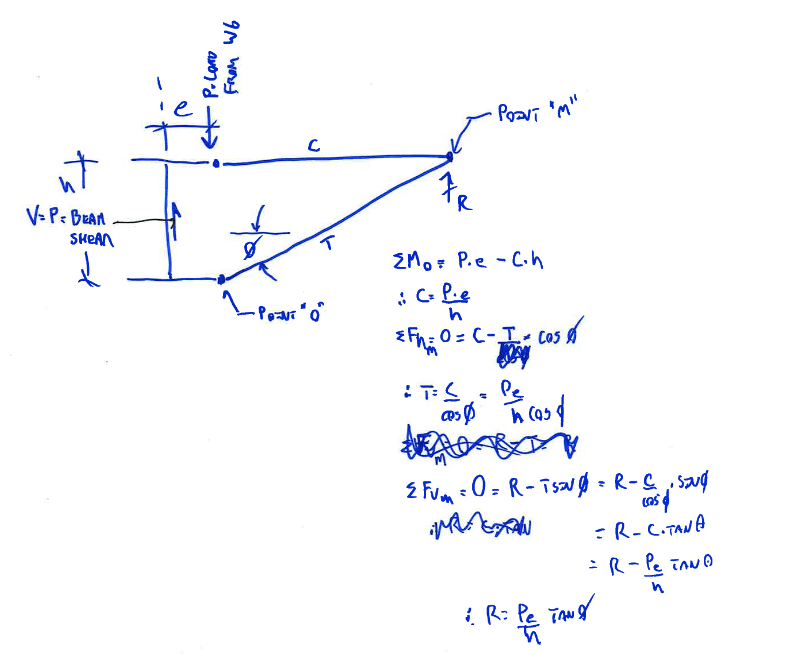
In my attachment, I started a concept for a new slab/floor beam/brace design. I don't love it, but I'm trying to improve the original design from the 1970s. I have concerns about applying torque on the W24 with a 10" eccentricity at the beam seat. Perhaps the L3x3x1/4 brace will counteract the torque, but I'm not confident in that. Please take a look at my FBDs and critique...I don't think they're quite right. I haven't worked with a system like this before. If it is right, I'm seeing that the original/existing design dumps a lot of axial load into the W24 from the offset brace connection. I'm trying to mitigate that with the new design.
In summary, what would be a good way to brace the W24 for LTB while avoiding large torque or dumping axial forces into it inadvertently? Thanks in advance

