Continue to Site

Eng-Tips is the largest engineering community on the Internet

Intelligent Work Forums for Engineering Professionals

  • Congratulations waross on being selected by the Eng-Tips community for having the most helpful posts in the forums last week. Way to Go!

Analyzing nelson studs welded diagonally for breakout 4

Status
Not open for further replies.

canwesteng

Structural
May 12, 2014
1,600
I'm analyzing some embedded plates with nelson studs welded in at an angle. I haven't had much luck finding this exact connection for some reason, even though it is pretty common. This is how I've decided to analyze it, kind of like some other precast connections, but wondering if there is a less conservative way to look at this.


nelson_stud_rdhrgk.png
 
Replies continue below

Recommended for you

You haven't had much luck finding a capacity check for this because it's normally an edging angle for protection of a corner, or some nominal force. It's a pretty awkward load path. There might be something in one of the precast manuals but I can't think of one at the moment.

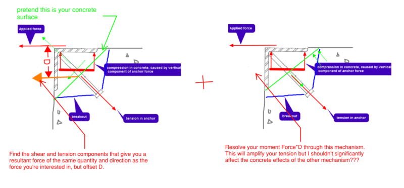
You could maybe do something like the attached. Draw your tension breakout cone and use that to find an imaginary concrete surface. Use that surface and edge distance to work out a compression and tension capacity for the embeded stud. Resolve out the moment between this resistance and your actual applied force using the second mechanism that should just induce some additional tension in the anchor. Take your force components plus your tension from the offset moment and compare to your capacity.

Screenshot_2023-09-26_181518_pjctaz.png
 
Concrete compression is on the wrong side on the second image
 
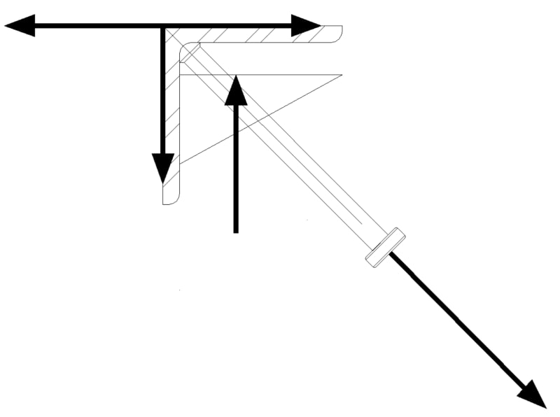
I'd likely design it something like

Clipboard01_wde9cp.jpg


with the vertical loads creating the moment to design the angle.

-----*****-----
So strange to see the singularity approaching while the entire planet is rapidly turning into a hellscape. -John Coates

-Dik
 
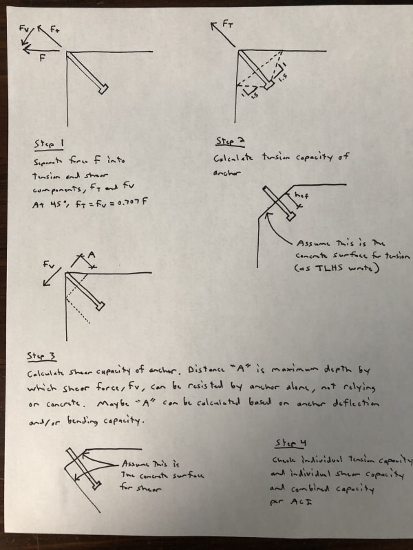
ACI 318, Chapter 17 (assuming that's what you're using) is seemingly limited to concrete surfaces which are orthogonal to the anchor axis. Therefore, I would design this as if concrete is removed in order to meet this condition. See sketches below.
headed_stud_at_45_degrees_b83mkt.jpg


I would feel confident using the tension capacity calculated above. The method used to determine the shear capacity, though, is perhaps a little questionable. I think it really comes down to how stiff the anchor is and how far into the concrete it can transfer the force without the concrete first failing.
 
dik - I think that is what I'm doing, isn't it?
TLHS - I think I understand what you're going for, but that seems quite a bit more conservative than my original plan. I suppose there might be some unresolved moment in my sketch, but I can likely justify a very small compression block near to the point of load application.
 
Pretty much... noted how I would design it; because of the lack of stiffness to the angle leg, I would use a triangular load as shown as opposed to a UDL.

-----*****-----
So strange to see the singularity approaching while the entire planet is rapidly turning into a hellscape. -John Coates

-Dik
 
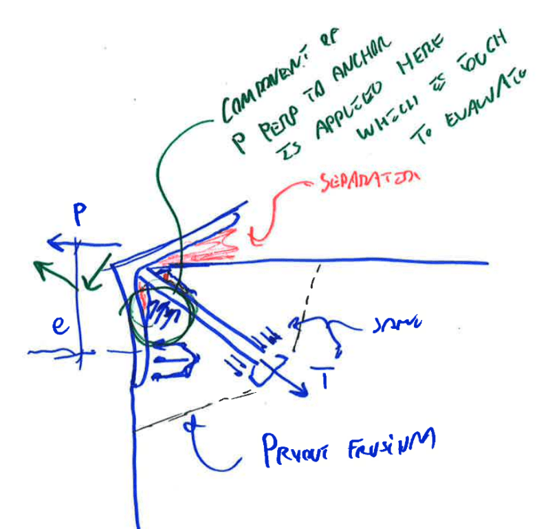
@canwest, dik, TLHS: all of these models that show the horizontal leg of the angle in compression against the slab are junk. The applied loads are going to tend to pull the horizontal leg away from the concrete. You're letting your FBD's interfere with your intuition and common sense.
 
Something like this with the big challenges being:

1) Evaluating this particular pryout frustum.

2) Evaluating the ability of the anchor to deliver shear to a non-orthogonal concrete surface at the base of the stud.

c01_rct1el.png
 
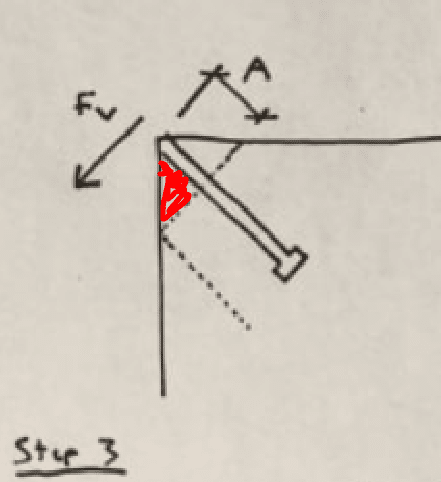
@ENG16080: I agree with most of your approach as a conservative estimate of capacity. My only serious problem with it is that it probably means pulverizing the bit of concrete shaded in red below. So it would be a one and done kind of situation.

c01_essn1q.png
 
I think the loads on this connection are a far cry from crushing the concrete. The breakout strength of the single anchor is not all that high, so the compressive stress on the concrete itself is low. This is an old structure that wasn't necessarily detailed all that well originally (some existing problems are why we are looking at it), but I feel like I have some plausible approaches for assessing the connection here, none of which will see the connection be strong enough.
 
In the solution by dik, I don't think the FBD is correct. Summing the moments about the point where the stud and angle intersect does not give zero. It seems like the stress distribution under the horizontal angle leg would need to be infinite at the left end for this to work out.
 
KootK, in my sketch where you shaded it red, the analysis conservatively assumes no concrete there outside the dotted lines (see sketch further down the page). Similar to what you wrote, I was considering that area as potentially crushing and therefore having minimal capacity.
 
Eng16080 said:
KootK, in my sketch where you shaded it red, the analysis conservatively assumes no concrete there outside the dotted lines (see sketch further down the page). Similar to what you wrote, I was considering that area as potentially crushing and therefore having minimal capacity.

Yup, I picked all of that up from your excellent sketches. That's why I said that it represented a "one and done" situation. The capacity determined by your method would prevent an all out catastrophe but, at the same time, probably represents permanent damage and movement. That would be en route developing what would be, effectively, an aggressive anchor standoff condition.

Eng16080 said:
It seems like the stress distribution under the horizontal angle leg would need to be infinite at the left end for this to work out.

Yes, and I take that as a more mathematical way of expressing my view that the horizontal angle leg pulls away from the concrete under load.

canwesteng said:
I think the loads on this connection are a far cry from crushing the concrete.

It likely would not be crushing of the concrete but, rather, something akin to a worsened version of individual anchor pryout or a separate, local version of shear breakout at that red triangle. This is the sense in which I meant that the concrete would be "pulverized". But, yeah, I see it now... pulverized does sound a lot like being crushed.
 
I wonder about that pry out mode (with the applied moment). I'm not sure if I've seen anything in (current) code that shows a (official) pressure distribution on the stud in that situation. The code certainly considers pry out.....but everything I've read shows that failure mode as being [pressure on] one side only.
 

incorrect... if the headed stud goes into tension, there is a resultant compressive force, else the clip angle accelerates.

-----*****-----
So strange to see the singularity approaching while the entire planet is rapidly turning into a hellscape. -John Coates

-Dik
 
dik said:
incorrect... if the headed stud goes into tension, there is a resultant compressive force, else the clip angle accelerates.

Tough talk from a guy who's FBD isn't even in equilibrium.

My model with the top leg of the angle separating from the concrete does not induce any angle "acceleration".
 
WArose said:
The code certainly considers pry out.....but everything I've read shows that failure mode as being [pressure on] one side only.

Exactly. I've no doubt that the setup has some capacity. It's just very difficult to apply any of the existing provisions confidently in the absence of related testing. And ACI specifically excluding the condition doesn't inspire much confidence either. I assume that the condition is excluded precisely because ACI recognized some of the complexity that we've been discussing here.
 
I agree with Koot's direction of forces, that's what I was saying about my compression block being drawn on the wrong side. It's on the left/bottom, not the right/top. I was just too lazy to draw it again and it didn't really affect my overall concept other than having the rotation direction wrong. I also don't really think it makes sense to draw the compression on the leg of the angle unless you're going to follow it further after evaluating the bending of the angle leg. That compression is inside the failure cone. It has to resolve along a concrete failure plane somewhere for the moments and things you derive from it to make sense in determining additional forces on the anchor.
 
fwiw. when I worked for a precaster we would bend the studs and alternate them on each leg.

nelson_sud1_wcjafs.png
 
Status
Not open for further replies.

Part and Inventory Search

Sponsor