Continue to Site

Eng-Tips is the largest engineering community on the Internet

Intelligent Work Forums for Engineering Professionals

  • Congratulations waross on being selected by the Eng-Tips community for having the most helpful posts in the forums last week. Way to Go!

Analyzing nelson studs welded diagonally for breakout 4

Status
Not open for further replies.

canwesteng

Structural
May 12, 2014
1,601
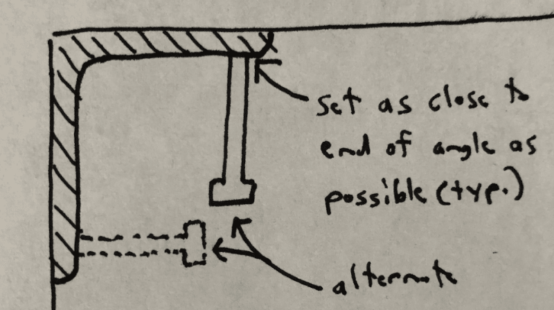
I'm analyzing some embedded plates with nelson studs welded in at an angle. I haven't had much luck finding this exact connection for some reason, even though it is pretty common. This is how I've decided to analyze it, kind of like some other precast connections, but wondering if there is a less conservative way to look at this.


nelson_stud_rdhrgk.png
 
Replies continue below

Recommended for you

wrantler,

I like that detail much better than the original, but I don't see the point in bending the studs. It seems like they'll want to straighten under tension load, crushing the concrete at the inside of the bend. What's the purpose of the bend? Increased cover distance?

I would consider this a better detail:
Stud_Detail_Alternative_bvuyvu.png

Any issues with this?
 
Eng16080, the problem with that detail is fit around rebar in the concrete. If the angle is large enough, maybe you can fit around the bar, but if not you will hear a lot of complaining if they have to fish in bars or take things apart to fit the misc steel.

I suspect 90% of the engineers using this detail have their own preferences that are not based much on math. I have never used them for any significant loads. Most of the time we use this to support grating.
 
Headed studs into the angle fillet at an angle, is likely the least costly.

-----*****-----
So strange to see the singularity approaching while the entire planet is rapidly turning into a hellscape. -John Coates

-Dik
 
Brad805, That's a good call regarding rebar interference. Of course, moving the studs closer to the concrete edge to avoid interference just results in less capacity for the lateral force shown in the diagram top of page. As you mentioned, I've never used this detail for significant loads, although gravity and in plane shear are probably ok. I doubt the original detail is good for much more than 1 kip of resistance for the load shown. It would be interesting to see test data on this.
 
The detail I showed was mostly to restrain the angle leg without becoming a burden for fitting with the existing rebar. If you only put a stud in the joint the angle legs are floating and if something catches them they will just bend up as KootK pic suggests. This angle detail is not good no matter how you place the studs. You can try and put breather holes but the concrete will never fully bear under the angle. If the angle is not under cyclic loading it prob doesnt matter tho.
 
All good discussion, but this is existing detail. I'd never detail something like this to resist real loads.
 
I also agree.

In case it's of any value, I was curious about this connection and ran some quick numbers based on my procedure above. I found that a single 8" long, 3/4" diameter anchor embedded in 3,000 psi concrete can resist a maximum factored lateral force (LRFD) of 1,100 lbs. The analysis assumes there is no concrete above the line connecting the sides of the tension failure surface, so it's as if the anchor is sticking above the concrete surface (about 5") with the load applied at the top. With the anchor projecting that much, it's close to failing in bending and deflects about 1/16", which I assume might cause the concrete at the top to crush/break off.

I wouldn't be surprised if the real capacity is higher than this, as I'm neglecting any potential benefit of the angle. Also, I'm guessing there's more than just one anchor attached to the angle.
 
The analysis assumes there is no concrete above the line connecting the sides of the tension failure surface, so it's as if the anchor is sticking above the concrete surface (about 5") with the load applied at the top. With the anchor projecting that much, it's close to failing in bending and deflects about 1/16", which I assume might cause the concrete at the top to crush/break off.

I've been thinking about this quite a bit over the last few days. I went to the bible of concrete anchors (i.e. 'Anchorage in Concrete Construction', by: Eligehausen, et al, published in 2006), and the failure of the concrete (for a single anchor with a cantilevered load) isn't covered. It is for steel however (see p.107-109). In the intro to the section, they say: "Flexural failure of the steel rod generally defines the capacity of such anchorages provided the distance to the edge of the component is sufficiently large."

One interesting thing this reference does is define the cantilever length....and it's longer than you'd think: it goes into the supporting concrete surface by about 0.5*the shank diameter.

So based on all this, probably the design approach for this situation would be:

1. Checking the steel capacity via the method talked about above....probably superimpose that utilization on top of the other code requirements for shear and tension.

2. Make sure you are embedded deep enough where pry out can't happen.

3. To get a warm/fuzzy feeling, check the anchors via some kind of acceptable stress distribution/embedment formula. In the thread linked to below (in my post @ 6 Sep 21 19:15), there is such a approach. It's meant for steel members in concrete....but it could probably work here.


4. As a back check for step #3, figure the couple (via the info in the link) and add that shear (closest to the surface) to the directly applied shears, and check as per allowable(s) in Chapter 17 of ACI 318 (i.e. concrete breakout and so on).
 
WARose, What you've described above is essentially how I analyzed this. I checked the typical concrete failure modes per ACI 318, Chapter 17. I then checked the steel anchor for failure per AISC, checking bending, shear, tension, and combined tension and shear per Section J3.7. The limiting capacity was found to be the combined tension and shear check, with the bending check not far off. As you mention above, I found the steel capacity of the anchor to be controlling the strength rather than concrete failure.

I didn't account for an increase in the cantilever length as you mentioned above, but it seems logical to do so. I also assumed that the anchor is bending in double curvature, so I used a lever arm of half the cantilever length to calculate the moment. I'm not certain this is entirely right for this application though. I would need to think about it more. Basically, I followed the procedure per AISC Design Guide 1, as outlined at the top of p. 29. If instead, a lever arm of the full cantilever length was used plus the additional distance of "0.5*the shank diameter" into the concrete that you mention, that would seemingly limit the capacity of the connection by more than half, so maybe then it would only be good for about 500 lbs.

I'll have to see if I can get a copy of that reference you mention.
 
If instead, a lever arm of the full cantilever length was used plus the additional distance of "0.5*the shank diameter" into the concrete that you mention, that would seemingly limit the capacity of the connection by more than half, so maybe then it would only be good for about 500 lbs.

Maybe that's a good thing. [smile] Considering this is unknown territory as far as the code goes.
The more I think about it, the more I think step #4 in my proposed check for this is essential. (More essential than step 3.) Step 3 doesn't really take into account the boundaries/edges of the concrete in question.
 
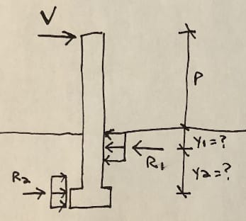
WARose, Regarding your step #4, I wasn't considering the capacity of the concrete to resist the moment from the anchor in my analysis above, but you're right about needing to do that if the anchor is being idealized as projecting above an effective concrete surface. I didn't have time to go through the other thread fully, but my understanding is that, per the sketch below, you would design the concrete shear strength based on the reaction R1 rather than V, which in this case is going to be much larger.
anchor_overturn_zazd1m.jpg

Really, I imagine you'd want to check the concrete shear capacity for both reactions R1 and R2, and that you'd also want to check concrete bearing strength at those locations. Where you now have prying forces acting on the concrete in opposing directions, I wouldn't be confident that the ACI provisions are applicable anymore. It seems this is getting further from the intent of the code.

Without running any numbers, by adopting your step #4 into my procedure, I think the connection capacity would now be much less, probably negligible.

Possibly....of course that's where lots of embedment pays off.

To handle the R[sub]1[/sub] & R[sub]2[/sub] of your sketch, I'd propose (as a process of my step 4) check R[sub]1[/sub]+V against the allowable breakout, etc at a depth where the load distribution for R[sub]1[/sub] ends (i.e. deeper than y[sub]1[/sub]). If you've got that capacity....you are probably (by inspection) ok @ R[sub]2[/sub].
 
I would change the configuration of this detail if you want it to take sig loading in the horizontal direction. There are many ways to do this. I just dont think a nosing angle with only angled studs is the way.

You could add u bars with horiz bars etc. not saying that is the good way to go tho.
 
Status
Not open for further replies.

Part and Inventory Search

Sponsor