Continue to Site

Eng-Tips is the largest engineering community on the Internet

Intelligent Work Forums for Engineering Professionals

  • Congratulations KootK on being selected by the Eng-Tips community for having the most helpful posts in the forums last week. Way to Go!

Irregular square-like feature. Square symbol applicable or not? 1

Status
Not open for further replies.

Wuzhee

Automotive
Jul 12, 2022
275
Hi,

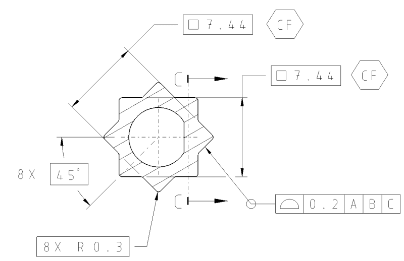
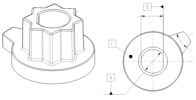
It's time for me to revisit my old friend, the square symbol. The star shaped bar is a torque-transfer mating interface for a BLDC actuator.
Parallel planes are 7.44 mm at the given distance (there's a measuring section plane not shown). I want to get lazy and not dimension everything. Can I square symbol this, with CF attached? I don't see a problem with it. ASME lacks in giving examples of square like features where this could be applied.

Also, the entire star shape is tapered by 0,5° between planes. How to adress the profile if I want to control the 3D surface not just a section of it? (Theoretically, because I don't want to increase CMM time and quality costs)

DRF picture
SQS1_f1eby5.png

Square tolerancing
SQS2_om7byv.png
 
Replies continue below

Recommended for you

The square shape is implied because of the right angles. You could specify the basic dimension as 2X 7.44. I don't see a benefit in using the square symbol, even though the intent is clear. CF next to a basic dimension is not appropriate because the purpose of this symbol is to communicate that separate portions of an interrupted feature are to be treated as one feature for any tolerance specification and conformance evaluation. In your case, it is already taken care of by the all around symbol that groups all the peripheral surfaces into a single controlled feature.

One remark that I have regarding the profile tolerance is that if you intend to apply it in a cross-section profile of a line is the proper symbol for that.
I don't think the reasoning of not wanting to control the entire surface to avoid additional CMM work is correct, but that's for a different topic.
 
I will say no, you cannot add the CF symbol here. The callout of star shape remains the same without any changes, so you cannot add the CF symbol just because you are using the 2009 standard (CF symbol added in 2009 version).

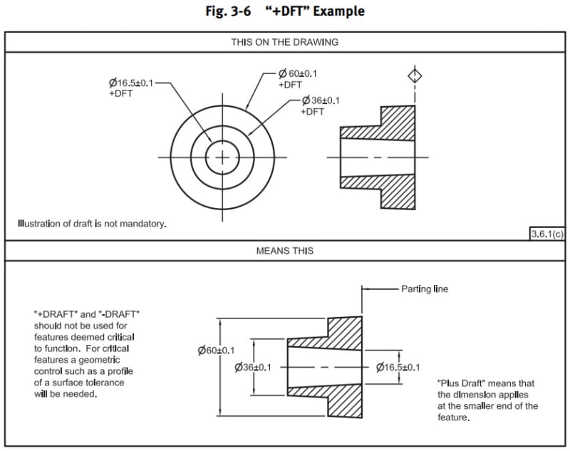
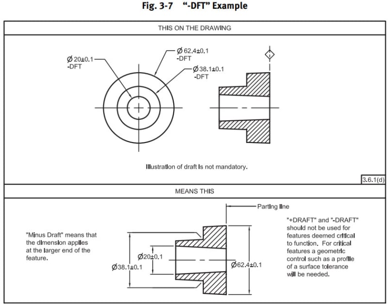
As for the 0.5° draft angle, you may apply the +DFT or -DFT(ASME Y14.8 Castings, Forgings and Molded Parts) on your print, but you need to decide which ends is you functional dimension, please see the pictures below for more detailed information.

2023-10-13_202919_zbiuip.jpg


2023-10-13_202949_tfflq8.jpg


Season
 
Thanks Burunduk & SeasonLee!

Another question about CF (not related to this topic but if we already spoke about CF...).
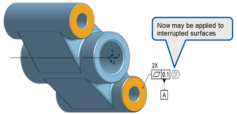
Can CF be applied if the 2 featured of size has different thickness? See below.

What is the better of the two? Adding the CF to Datum A or adding "2X" to the FCF?

CF1_c3dded.jpg

CF2_trrszf.jpg
 
I'm not sure how your last question relates to features of size or thickness.
The flatness tolerance is applied to two coplanar faces. The CF symbol can be used next to the flatness FCF to impose coplanarity within the flatness tolerance.
2X can be placed before the datum feature symbol (beneath the flatness FCF) to indicate that the datum is established from both surfaces at the same time, if this is your intent.
 
I was just confused about FoS and CF callout.

The requirement is coplanarity between the two surfaces. So I need both of them? CF after flatness AND 2X before Datum A. Am I getting your message right?
 
Yes, this is the way I would do it, although I can predict that some would argue that the 2X before the datum feature symbol is not necessary if there is a CF symbol associated with the flatness callout.

Another alternative is this:
Screenshot_20231013_174029_Drive_hyiijj.jpg
 
I kept both because who knows how many people understand it differently.
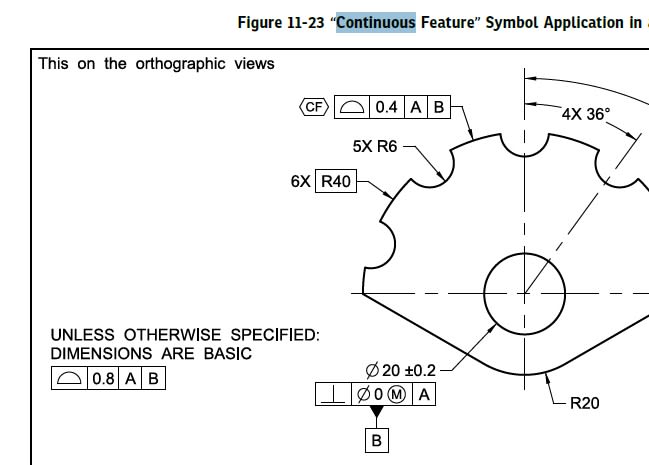
2018 edition Figure 11-23 has a similar solution.
11-23_oav7ic.jpg
 
Glad to know that you find out the solution by yourself.

Burunduk said:
I'm not sure how your last question.....
Frankly speaking, I don't understand your last question either.

Season
 
The Square symbol indicates it is not a rectangle in spite of the apparent right angles. A single [2X 7.44] would work with CF as there are 2 interrupted features, though there are 4 pairs of opposing planes so [4X 7.44] would be the most accurate when used with a profile of line/profile of surface tolerance.

CF was designed to get around specifying surface counts, which can be difficult for MBD systems to automatically determine as the creation of the interruption can be after the creation of the interrupted surface. Previously it was implied with extension lines. It is also helpful on width features when there are a different number of interruptions (example a slot or rib on one face) than the other, making the count ambiguous.

There is need for only on [45 degree] referece; a single [135 degree] angle between adjacent convex flats would also be sufficient.
 
Wuzhee, here is a side note:
The way your drawing looks, you probably made it with Catia.
I suppose you know this is an incorrect display of the datum feature symbol:
Screenshot_20231013_225130_Chrome_zztjc0.jpg

I haven't found an easy way to show it properly on the direct view of a surface in Catia, either.
The way I've been doing this is adding a leader directed text note with just an underscore as the text, then attaching the datum feature symbol by the triangle to the horizontal portion of the leader.
 
The datum symbol triangle has been the greatest redundant piece of drawing decoration ever! So glad ASME copied off the ISO team's homework to steal this really useless idea.
 
Wuzhee
I think this is the example you wanted: both CF symbol and the quantity 2X appeared on the print.

2023-10-14_115351_dl65q5.jpg


Season
 
So the workaround is to place a FCF, a qualifier every planar datum feature should have, and dangle the toilet plunger from the FCF. That should be the easy way.
 
If this is molded a parting line across the corners of the squares will leave nearly no draft required on contacting surfaces. Pins can go in from the sides for the D-shaft which will reduce the section variation for a better fit. Aligning the parting line with the tab will also make a better tab side surface.

It also allows the option of crowning any of the contacting surfaces.
 
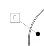
Burunduk, Datum C is shown in the main view, this is a cut of the original drawing (without any further info, because intellectual property). I just repeated it here.
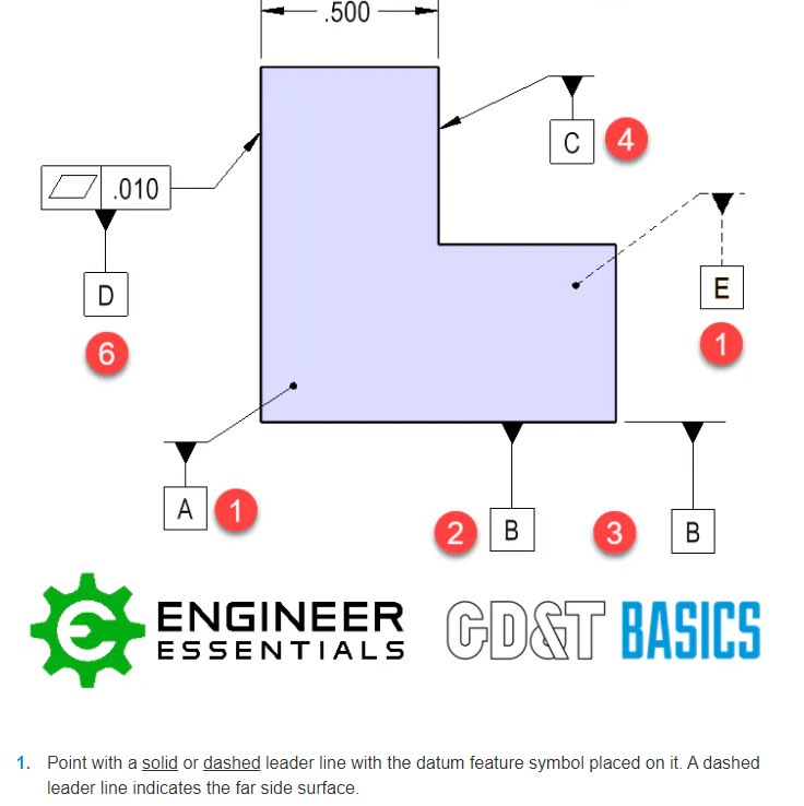
Also, look at these pesky GD&T basics guys.
datum_xblyc1.jpg

By the way I'm not using this normally on my drawings.

me said:
Can CF be applied if the 2 featured of size has different thickness? See below.
Burunduk said:
I'm not sure how your last question relates to features of size or thickness.
SeasonLee said:
Frankly speaking, I don't understand your last question either.
I assumed because the two datum planes are one half of different thicknesses, my idea was that CF is not valid in this case because one FoS have a thickness of 6 mm and the other has less (1.7 or 2, does not really matter) But I realized quickly it's bs and forgot to address the confusion later on.
 
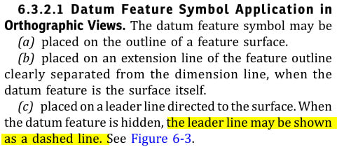
Dashed line can be used only on the leader line when the datum feature is on the far side, not on the datum feature symbol line. please see the picture below.

2023-10-16_060227_oayzbc.jpg


Sorry for I still cannot understand your question.

Season
 
There's no question anymore, because I realized I was wrong. Sorry for confusion.
I know the guys at that company make some mistakes in their figures, I just pasted it for reference related to the dotted leader line Datum C.
I would never use this datum feature symbol on a real drawing.
 
Wuzhee said:
Also, look at these pesky GD&T basics guys.
Just making sure - you do notice the difference in the symbol display between their figure (datum feature symbol A), and your/original drawing's datum feature symbol C, right?
 
Wuzhee said:
I would never use this datum feature symbol on a real drawing.

Why? I find handy sometimes, minus the technical difficulty which I mentioned.
 
Status
Not open for further replies.

Part and Inventory Search

Sponsor