Continue to Site

Eng-Tips is the largest engineering community on the Internet

Intelligent Work Forums for Engineering Professionals

  • Congratulations KootK on being selected by the Eng-Tips community for having the most helpful posts in the forums last week. Way to Go!

Wind Pressure on Gable Frame that is Distributed to Columns and Rafters

Status
Not open for further replies.

Tygra_1983

Student
Oct 8, 2021
121
Hi all,

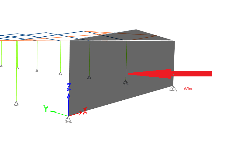
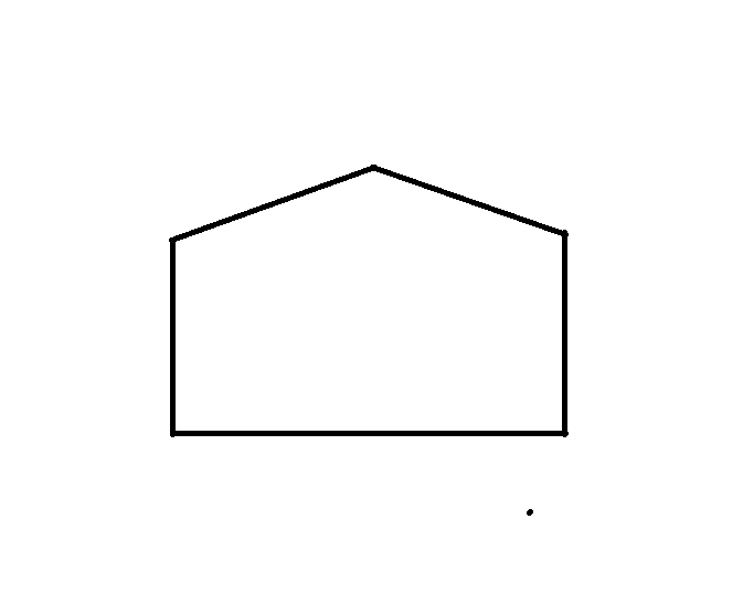
If I have a basic gable frame such as the one below that has a wind pressure acting on it (say 1 kN/m^2). What is the best way to distribute this pressure to the columns and rafters as UDL's in kN/m? The pitced roof section is giving me a bit of a headache. Im not sure how to apply the pressure to the diagonal rafters to get kN/m. Please note, the wind pressure is acting on the frame into the screen.
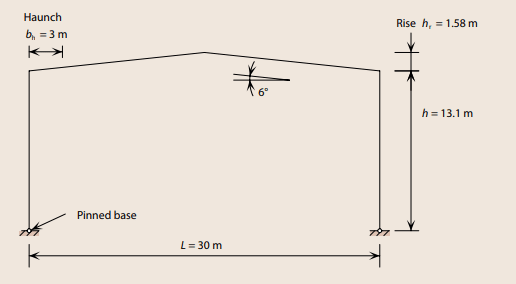
portal_gdyteq.png


Many thanks
 
Replies continue below

Recommended for you

You can consider the vertical projected area of the roof (in your case 1.58) and apply the lateral wind pressure to that.

But the presumption that the wind pressure on a sloped roof is the same as the walls I think is wrong.

Generally wind pressure on roofs is a different magnitude than the walls, and has different directions.

If your just interested in the lateral design of the frame the first approach I mentioned should work pretty well. Just assume the walls go all the way to the ridge and the roof is flat, cant get worse than that really.

If your interested roof pressure into and out of your roof system you need to take a more sophisticated approach to wind pressure. Simply saying 1 kN/m2 is not clear.
 
What I am asking is if a pressure of 1 kN/m^2 is applied to the surface of the gable frame like below:

wind_gable1_wlwty3.png


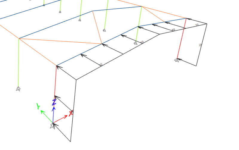
How do I calculate the UDL which acts on the rafters and columns like this:

load_mdd6zz.png


Ignore the 10 kN/m. I just wanted to show the projected load on the gable frame.
 
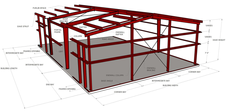
Gable Ends typically have vertical intermediate columns (called wind columns). Your sketches are not showing these. These end wall columns may (or may not) be slotted vertically at the roof, so they will not transfer gravity loads. In the USA these columns are typically 20 to 25 feet apart. Horizontal girts span between the corner columns and the wind columns. The portal frame will be loaded with concentrated wind loads at the end of the girts and the top of the wind columns. At each wind column, about half of its wind load will go to the roof and half to the ground.
 
I really don't think you are understanding what I am asking. To rephase my question say you have a panel on a floor like the following:

Untitled_xrmjmg.png


Say there is 1 kN/m^2 of pressure on this panel. What is the loading in kN/m at the edges (beams)?
 
Generally the wall sheathing spans Vertically to wall girts. Girts are like beams that span horizontally to columns called wind columns.

So your roof system will see a UDL w/ half the height tributary effectively, or a series of point loads often spaced at 20-25' o.c. in the US.

The columns on the end will see a UDL with a tributary of half the distance to the next over wind column. Or more precisely a series of point loads at the girt spacing.

20201103154509-omb-3d-building-2-12-new-001jpg_c6zygw.jpg
 
Status
Not open for further replies.

Part and Inventory Search

Sponsor