Eng-Tips is the largest engineering community on the Internet

Intelligent Work Forums for Engineering Professionals

  • Congratulations waross on being selected by the Eng-Tips community for having the most helpful posts in the forums last week. Way to Go!

steam pressure transmitter

Status
Not open for further replies.

rika kose

Chemical
Jun 11, 2019
51
NL
A steam manifold needs a PT. Saturated steam 10 barg 185ºC.
Vendor suggests a PT which has to be installed 1.5m away from the steam manifold.
A 1.5m tubing will cool the steam to fit the PT.

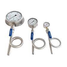
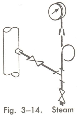
I see the siphon tube on PT very often.

My question is will the 1.5m tubing also reduce pressure? IS the measured pressure steam pressure.

Thanks

 
Replies continue below

Recommended for you

Without seeing the layout its not easy to say exactly - Is the 1.5m vertically up or horizontal or??

Syphon tube?

Generally impulse lines should be self draining no?

But in essence yes, even if you get water condensate slugs it will give you the steam pressure.

There is no flow normally, but please post the details.

Remember - More details = better answers
Also: If you get a response it's polite to respond to it.
 
Like this? Pretty common for steam applications.
Steam_Siphon_c2ycx7.jpg


It'll be mostly line pressure. A 1.5m "pig-tail" steam siphon is likely around 0.75m high. Perhaps half of that height is in the riser from the header, so you'll have, at most, approximately 0.25-0.4m or so of head loss from the condensate during operation. Since there is usually air in the siphon before startup, the actual measurement error will be the differential head of the condensate in the loop. This is minimized because air will be compressed on the gauge-side of the condensate, limiting upward rise due to the steam pressure.

All in all, you're probably looking at 1-2 kPA error, at most.
 
Thanks for the replies.

The 1.5m tubing is not pig tail type. I call the pig tail siphon tube.
It is a "L" shape tube, vertical piece around 1m, horizontal piece(slope) 0.5m.

 
If this is continually sloped back to the top/side of the header, then there will be no significant change in measured pressure; the formed condensate from heat loss will just drain back down. Why put this in rather than direct mounting? You will be exposing your instrument to full steam temperature in either case (I hope the instrument is rated for it!).
 
Impulse lines are dead headed so there's no flow to continually add heat over time. But for steam, a water barrier is needed to keep the steam away from the instrument's sensing diaphragm.

Run some horizontal tubing away from the pipe and install a siphon vertically on the end horz tube and then mount the transmitter (if it is an in-line style). Fill the siphon with water to keep the steam away from the instrument's sensing diaphragm. Condensed steam will keep the lower half of the siphon filled over time.

Steam_impulse_tube_with_siphon_pigtail_for_PI_gauge_vipy14.jpg


If it's a smart transmitter with process heads with the port on the side, you can mount like the one shown below, but with only one impulse line running to the pressure port. The tee at J1/J2 is used to fill the impulse lines with water. A smart transmitter will have a parameter setting to subtract out the head pressure of the water in the impulse lines.

Steam_DP_vertical_down_flow_mnwhsv.jpg
 
Status
Not open for further replies.

Part and Inventory Search

Sponsor

Back
Top