Continue to Site

Eng-Tips is the largest engineering community on the Internet

Intelligent Work Forums for Engineering Professionals

  • Congratulations IDS on being selected by the Eng-Tips community for having the most helpful posts in the forums last week. Way to Go!

Direct Stiffness Method Help

Status
Not open for further replies.

Tygra_1983

Student
Oct 8, 2021
121
Hi all,

I am trying to solve for a gable frame using the Direct Stiffness Method. The frame is obviously constructed of two rafters and two columns. I am quite confused: I am getting the correct results for the columns, but not for the rafters. I am comparing my results to those in ETABS for confirmation of the correct results. I am using my beloved Octave, so I need someone who uses either Octave or MATLAB.

The frame consists of two 8 metre columns, and two 15.083 metre rafters at an angle of 6 degrees to the horizontal. The UDL on the rafters is 13.14 kN/m
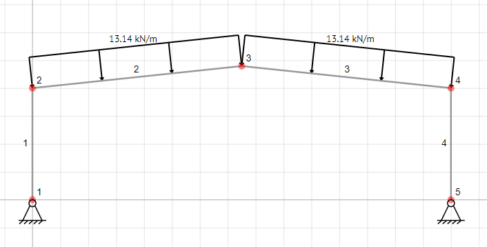
combined_loading_bfo8dl.png


Here is the code from Octave:

Code:
clear, clc, close all

[b]% Structural data[/b]

     E = 2.1E+08;
     Ic = 8.74999E-04;  [b]Second Moment areas of Columns[/b]
     Ac = 0.01442;      [b] Cross-sectional areas of columns[/b]
     Lc = 8;
     n = 15;
     alpha = 6          [b]Slope of roof in degrees[/b]
     matrix = zeros(6,n);
     Lr = 15/(cosd(alpha))
     Ir = 2.94331E-04   [b]Second Moment areas of rafters[/b]
     Ar = 0.00856;       [b] Cross-sectional areas of rafters[/b]

     [b]% Local stiffness matrix for columns[/b]

     Kc = [1 0 0 -1 0 0
           0 12 6*Lc 0 -12 6*Lc
           0 6*Lc 4*Lc^2 0 -6*Lc 2*Lc^2
          -1 0 0 1 0 0
           0 -12 -6*Lc 0 12 -6*Lc
           0 6*Lc 2*Lc^2 0 -6*Lc 4*Lc^2]

      [b]% Local stiffness matrix for rafters[/b]

      Kr = [1 0 0 -1 0 0
            0 12 6*Lr 0 -12 6*Lr
            0 6*Lr 4*Lr^2 0 -6*Lr 2*Lr^2
           -1 0 0 1 0 0
            0 -12 -6*Lr 0 12 -6*Lr
            0 6*Lr 2*Lr^2 0 -6*Lr 4*Lr^2]

       [b]% For loop to complete the local stiffness matrices[/b]

       for i = 1:6
            if i == 1 || i == 4
            Kc(i,:) = Kc(i,:)*(E*Ac)/Lc;
            Kr(i,:) = Kr(i,:)*(E*Ar)/Lr;
           else
           Kc(i,:) = Kc(i,:)*(E*Ic)/Lc^3;
           Kr(i,:) = Kr(i,:)*(E*Ir)/Lr^3;
             end
         end  

      [b] % Transformation matrices[/b]

       T1 = matrix; [b]For Left Column[/b]
       T1(2,1) = -1;
       T1(1,2) = 1;
       T1(3,3) = 1;
       T1(5,4) = -1;
       T1(4,5) = 1;
       T1(6,6) = 1

       T4 = matrix; [b]For right column[/b]
       T4(2,13) = -1;
       T4(1,14) = 1;
       T4(3,15) = 1;
       T4(5,10) = -1;
       T4(4,11) = 1;
       T4(6,12) = 1;


       T2 = matrix;
       T2(1,4) = cosd(alpha);   [b]For left rafter[/b]
       T2(1,5) = sind(alpha);
       T2(2,4) = -sind(alpha);
       T2(2,5) = cosd(alpha);
       T2(3,6) = 1;
       T2(4,7) = cosd(alpha);
       T2(4,8) = sind(alpha);
       T2(5,7) = -sind(alpha);
       T2(5,8) = cosd(alpha);
       T2(6,9) = 1;

       T3 = matrix;
       T3(1,7) = cosd(-alpha);  [b]For right Rafter[/b]
       T3(1,8) = sind(-alpha);
       T3(2,7) = -sind(-alpha);
       T3(2,8) = cosd(-alpha);
       T3(3,9) = 1;
       T3(4,10) = cosd(-alpha);
       T3(4,11) = sind(-alpha);
       T3(5,10) = -sind(-alpha);
       T3(5,11) = cosd(-alpha);
       T3(6,12) = 1;

       [b]% Assembly[/b]

       km1 = T1'*Kc*T1;
       km2 = T2'*Kr*T2;
       km3 = T3'*Kr*T3;
       km4 = T4'*Kc*T4;

       Ks = km1 + km2 + km3 + km4

     [b] % Application of boundary conditions[/b]

      Ks(:,[1,2,13,14]) =[];
      Ks([1,2,13,14],:) =[];

      [b]% Applying loading[/b]

      w = 13.14;
      V = w*Lr/2;
      M = w*Lr^2/12;

      F = zeros(n,1);
      F(4) = -V*sind(alpha);
      F(5) = V*cosd(alpha);
      F(6) = M;
      F(8) = 2*V*cosd(alpha);
      F(9) = 0;
      F(10) = V*sind(alpha);
      F(11) = V*cosd(alpha)
      F(12) = -M;
      F([1,2,13,14]) = []

      [b]% Solving[/b]

      U = inv(Ks)*F

      Ux = [0 0 U(1:10)' 0 0 U(11)'];
      fx = T2*Ux'
      force = Kr*fx

The force vector gives the axial force, shear and bending moment for a single member over two joints. There are three degress of freedom at each joint.

This is the results for the column:

Code:
Ux = [0 0 U(1:10)' 0 0 U(11)'];
      fx = T1*Ux'
      force = Kc*fx
      
      force =

  -197.1000
   108.3198
          0
   197.1000
  -108.3198
   866.5586

These results are correct!!

These are the results for the rafter:

Code:
Ux = [0 0 U(1:10)' 0 0 U(11)'];
      fx = T2*Ux'
      force = Kr*fx
      
      force =

  -128.329
   -85.605
  -617.462
   128.329
    85.605
  -673.685

These results are incorrect!

I have examined everything and cannot see what is the issue. I know this question is quite time comsuming, so I deeply thank anyone that attempts to help!
 
Replies continue below

Recommended for you

Sorry guys, here are the full transformation matrices:

T1 (left column)

Code:
T1 =

   0   1   0   0   0   0   0   0   0   0   0   0   0   0   0
  -1   0   0   0   0   0   0   0   0   0   0   0   0   0   0
   0   0   1   0   0   0   0   0   0   0   0   0   0   0   0
   0   0   0   0   1   0   0   0   0   0   0   0   0   0   0
   0   0   0  -1   0   0   0   0   0   0   0   0   0   0   0
   0   0   0   0   0   1   0   0   0   0   0   0   0   0   0

T4 (Right column)

Code:
T4 =

   0   0   0   0   0   0   0   0   0   0   0   0   0   1   0
   0   0   0   0   0   0   0   0   0   0   0   0  -1   0   0
   0   0   0   0   0   0   0   0   0   0   0   0   0   0   1
   0   0   0   0   0   0   0   0   0   0   1   0   0   0   0
   0   0   0   0   0   0   0   0   0  -1   0   0   0   0   0
   0   0   0   0   0   0   0   0   0   0   0   1   0   0   0

T2 (left rafter)

Code:
T2 =

        0        0        0   0.9945   0.1045        0        0        0        0        0        0        0        0        0        0
        0        0        0  -0.1045   0.9945        0        0        0        0        0        0        0        0        0        0
        0        0        0        0        0   1.0000        0        0        0        0        0        0        0        0        0
        0        0        0        0        0        0   0.9945   0.1045        0        0        0        0        0        0        0
        0        0        0        0        0        0  -0.1045   0.9945        0        0        0        0        0        0        0
        0        0        0        0        0        0        0        0   1.0000        0        0        0        0        0        0

T3 (right rafter)

Code:
T3 =

        0        0        0        0        0        0   0.9945  -0.1045        0        0        0        0        0        0        0
        0        0        0        0        0        0   0.1045   0.9945        0        0        0        0        0        0        0
        0        0        0        0        0        0        0        0   1.0000        0        0        0        0        0        0
        0        0        0        0        0        0        0        0        0   0.9945  -0.1045        0        0        0        0
        0        0        0        0        0        0        0        0        0   0.1045   0.9945        0        0        0        0
        0        0        0        0        0        0        0        0        0        0        0   1.0000        0        0        0
 
Have you tried to use your m file and ETABS on a very easy problem first? That way you could manually generate everything quickly and see where your .m file is going wrong. The one in your first post isn't enormous, but it's a pretty big problem for manual calcs.

I'd try the following, because it seems like there's a good chance your rotation transformation might be the problem.

Single horizontal beam with axial force and end moments.

Single vertical beam with axial force and end moments.

Then step up to a two member frame with one vertical and one horizontal member. (Fix the ends of one member to cut down the DOFs.) This one is to test whether your member DOFs area mapping correctly to your structure DOFs.
 
Without going through the code step by step there are some checkpoints you may want to consider (maybe you have).

First is consistent units. There is a lot going on the DSM and plenty of places to mess up units. Ensure that you have properly converted all units as needed before the matrix solution begins.

Next question, when you say the results are wrong are we talking order of magnitude wrong or just a little bit off?

SAP2000 has the ability to include shear deflections which you are not doing here. So if you want a reasonable comparison ensure those shear deflections are neglected in SAP.

Finally you have used a zero stiffness assignment for your boundary conditions, ensure that in the solution phase you are properly partitioning the global stiffness matrix into restrained and unrestrained DOFs. Its easy for something to be lost in translation here.

 
are the results right for a column (EL 1) ?

the load on a column should be 13.14*15*cosd(6) = 196 kN ...
interestingly, 197 kN is 15*13.14 ... the inclined load on the roof ?

the six results for the column are three forces at either end, yes? why if force3 unbalanced
nah, more like 2 inplane forces and the inplane moment ... 108*8 = 864 ... ok, but that is a large lateral load on the column ...
surely the applied lateral load is 13.14*15*sind(6) ? wouldn't this be divided between the two ends of the roof ? (so the peak sees equal and opposite loads ?)

"Hoffen wir mal, dass alles gut geht !"
General Paulus, Nov 1942, outside Stalingrad after the launch of Operation Uranus.
 
Very quick pass but it looks like you did not consider the fixed end force vector when computing the Rafter results, need to either add or subtract the fixed end force vector depending on what sign convention was used.

 
The strange thing is guys that the displacements over the whole frame are correct. This should surely give correct results.

271828 said:
Have you tried to use your m file and ETABS on a very easy problem first? That way you could manually generate everything quickly and see where your .m file is going wrong. The one in your first post isn't enormous, but it's a pretty big problem for manual calcs.

I'd try the following, because it seems like there's a good chance your rotation transformation might be the problem.

I tried a single cantilever beam at an angle and got correct results. At first I thought the transformation matrix for the rotation would be the culprit, but now I don't think it is.

driftlimiter said:
Next question, when you say the results are wrong are we talking order of magnitude wrong or just a little bit off?

We are talking order of magnitude. For the rafter, they results are way off.

My results:

Code:
force =

  -128.329
   -85.605
  -617.462
   128.329
    85.605
  -673.685

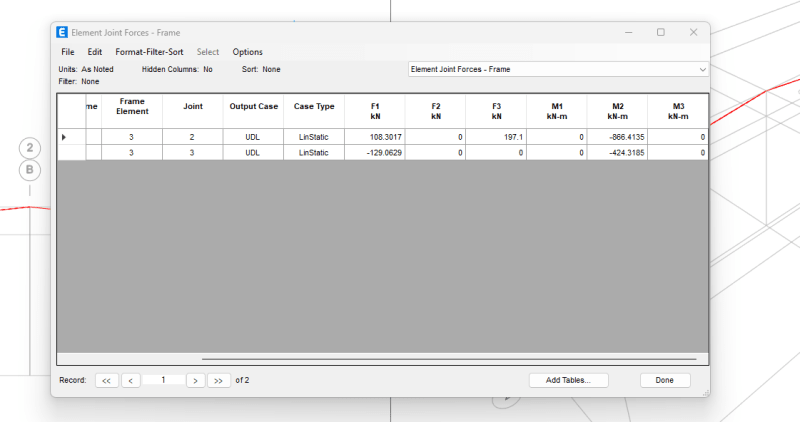
Results in ETABS:

results_gtkapx.png


Celt83 said:
Very quick pass but it looks like you did not consider the fixed end force vector when computing the Rafter results, need to either add or subtract the fixed end force vector depending on what sign convention was used.

Could you elborate a bit more please, Celt83? Do you mean at node 3 (central node) F(9) of the force vector?
 
So the general function when there are loads between nodes becomes:
K U = F + Ffixed

To recover F:
F = K U - Ffixed

Your Etabs result seems to indicate the axial force (F1) in the rafter changes over it’s length so either self weight is being considered or you have applied the load on the horizontal projection instead of perpendicular to the rafter local axis per your sketch.
 
The Etabs results you had in your screenshot are end forces in the global axis, your results are in the member local axis and also missing the fixed end reaction components.
 
These are the results I get

[pre]Displacements:
-----------------------------------------------
Node | Ux | Uy | Rz |
-----------------------------------------------
N1 | 0.0000E+00 | 0.0000E+00 | 1.1982E-02 |
-----------------------------------------------
N2 |-4.5528E-02 |-5.2071E-04 |-6.8902E-03 |
-----------------------------------------------
N3 | 3.2583E-15 |-4.4643E-01 | 1.9065E-16 |
-----------------------------------------------
N4 | 4.5528E-02 |-5.2071E-04 | 6.8902E-03 |
-----------------------------------------------
N5 | 0.0000E+00 | 0.0000E+00 |-1.1982E-02 |
-----------------------------------------------
-----------------------------------------------
Reactions:
-----------------------------------------------
Node | Fx | Fy | Mz |
-----------------------------------------------
N1 | 1.0837E+02 | 1.9710E+02 |-1.1369E-13 |
-----------------------------------------------
N2 |-1.0232E-12 |-1.9895E-13 |-2.2737E-13 |
-----------------------------------------------
N3 | 2.0748E-12 | 1.4211E-13 | 0.0000E+00 |
-----------------------------------------------
N4 | 5.6843E-14 | 8.5265E-14 | 2.2737E-13 |
-----------------------------------------------
N5 |-1.0837E+02 | 1.9710E+02 | 5.6843E-14 |
-----------------------------------------------
------------------------------------------------------
Member Local End Forces:
------------------------------------------------------
Member |joint | Ax | Vy | Mz |
------------------------------------------------------
M1 | i | 1.9710E+02 |-1.0837E+02 | 0.0000E+00 |
| j |-1.9710E+02 | 1.0837E+02 |-8.6692E+02 |
------------------------------------------------------
M2 | i | 1.2827E+02 | 1.8477E+02 | 8.6692E+02 |
| j |-1.2827E+02 | 1.3408E+01 | 4.2527E+02 |
------------------------------------------------------
M3 | i | 1.2827E+02 | 1.3408E+01 |-4.2527E+02 |
| j |-1.2827E+02 | 1.8477E+02 |-8.6692E+02 |
------------------------------------------------------
M4 | i | 1.9710E+02 | 1.0837E+02 | 0.0000E+00 |
| j |-1.9710E+02 |-1.0837E+02 | 8.6692E+02 |
------------------------------------------------------
------------------------------------------------------
Member Global End Forces:
------------------------------------------------------
Member |joint | Fx | Fy | Mz |
------------------------------------------------------
M1 | i | 1.0837E+02 | 1.9710E+02 |-1.1369E-13 |
| j |-1.0837E+02 |-1.9710E+02 |-8.6692E+02 |
------------------------------------------------------
M2 | i | 1.0837E+02 | 1.9710E+02 | 8.6692E+02 |
| j |-1.2897E+02 | 5.4001E-13 | 4.2527E+02 |
------------------------------------------------------
M3 | i | 1.2897E+02 |-3.9790E-13 |-4.2527E+02 |
| j |-1.0837E+02 | 1.9710E+02 |-8.6692E+02 |
------------------------------------------------------
M4 | i |-1.0837E+02 | 1.9710E+02 | 5.6843E-14 |
| j | 1.0837E+02 |-1.9710E+02 | 8.6692E+02 |
------------------------------------------------------[/pre]
 
Hi Celt83, I am getting the correct results now. So, I would like to thank you for taking the time to help me. Thanks so much!

I have another question if thats okay.

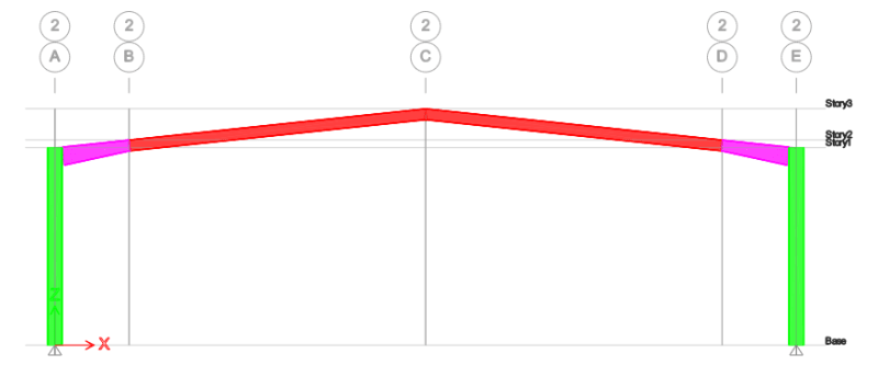
In ETABS, I am trying to replicate an Eaves Haunch. The way I have done this was to combine to seperate cross sections. One that tapers and one that is straight. Obviously, this creates a node joint between the members. So, my question is, will this combined member act as one single member, or is the joint (even though it is a rigid joint) not allow for the two seperate members to act as one single member? Because in the real world they weld a cut member to the bottom of the rafter to create the eaves haunch - not two seperate members.

Here is what it looks like:

haunch_jvlnn5.png


Thanks again!
 
From an analysis perspective as long as you have not applied any releases/hinges to the member ends then you can insert nodes at will and the behvaiour will be that of a continuous member, to satisfy this for yourself create some very simple models one with a single bar element support to support and one with several bar elements support to support. I usually like to test this with a fixed-free cantilever and verify the tip deflections are the same.

Where you need to be careful is in design because the member length will typically default to be node to node so this will impact unbraced lengths for column/beam designs. Typically software like Etabs, Stadd, etc will allow you to manually define Lb for each axis of the member to override the computed node-to-node distance.

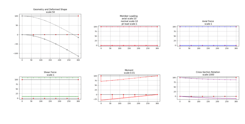
Here are my results for a simple fixed-free beam with a point load at the end (N6 and N8):
[pre]Displacements:
-----------------------------------------------
Node | Ux | Uy | Rz |
-----------------------------------------------
N1 | 0.0000E+00 | 0.0000E+00 | 0.0000E+00 |
-----------------------------------------------
N2 | 0.0000E+00 |-1.2874E-01 |-4.1379E-03 |
-----------------------------------------------
N3 | 0.0000E+00 |-4.7816E-01 |-7.3563E-03 |
-----------------------------------------------
N4 | 0.0000E+00 |-9.9310E-01 |-9.6552E-03 |
-----------------------------------------------
N5 | 0.0000E+00 |-1.6184E+00 |-1.1034E-02 |
-----------------------------------------------
N6 | 0.0000E+00 |-2.2989E+00 |-1.1494E-02 |
-----------------------------------------------
N7 | 0.0000E+00 | 0.0000E+00 | 0.0000E+00 |
-----------------------------------------------
N8 | 0.0000E+00 |-2.2989E+00 |-1.1494E-02 |
-----------------------------------------------
-----------------------------------------------
Reactions:
-----------------------------------------------
Node | Fx | Fy | Mz |
-----------------------------------------------
N1 | 0.0000E+00 | 1.0000E+01 | 3.0000E+03 |
-----------------------------------------------
N2 | 0.0000E+00 | 5.5778E-13 |-9.0949E-13 |
-----------------------------------------------
N3 | 0.0000E+00 |-4.5475E-13 | 0.0000E+00 |
-----------------------------------------------
N4 | 0.0000E+00 | 1.5916E-12 |-7.2760E-12 |
-----------------------------------------------
N5 | 0.0000E+00 |-1.8190E-12 | 0.0000E+00 |
-----------------------------------------------
N6 | 0.0000E+00 | 9.0949E-13 | 0.0000E+00 |
-----------------------------------------------
N7 | 0.0000E+00 | 1.0000E+01 | 3.0000E+03 |
-----------------------------------------------
N8 | 0.0000E+00 | 0.0000E+00 |-5.3380E-13 |
-----------------------------------------------
------------------------------------------------------
Member Local End Forces:
------------------------------------------------------
Member |joint | Ax | Vy | Mz |
------------------------------------------------------
M1 | i | 0.0000E+00 | 1.0000E+01 | 3.0000E+03 |
| j | 0.0000E+00 |-1.0000E+01 |-2.4000E+03 |
------------------------------------------------------
M2 | i | 0.0000E+00 | 1.0000E+01 | 2.4000E+03 |
| j | 0.0000E+00 |-1.0000E+01 |-1.8000E+03 |
------------------------------------------------------
M3 | i | 0.0000E+00 | 1.0000E+01 | 1.8000E+03 |
| j | 0.0000E+00 |-1.0000E+01 |-1.2000E+03 |
------------------------------------------------------
M4 | i | 0.0000E+00 | 1.0000E+01 | 1.2000E+03 |
| j | 0.0000E+00 |-1.0000E+01 |-6.0000E+02 |
------------------------------------------------------
M5 | i | 0.0000E+00 | 1.0000E+01 | 6.0000E+02 |
| j | 0.0000E+00 |-1.0000E+01 | 0.0000E+00 |
------------------------------------------------------
M6 | i | 0.0000E+00 | 1.0000E+01 | 3.0000E+03 |
| j | 0.0000E+00 |-1.0000E+01 |-5.3380E-13 |
------------------------------------------------------
------------------------------------------------------
Member Global End Forces:
------------------------------------------------------
Member |joint | Fx | Fy | Mz |
------------------------------------------------------
M1 | i | 0.0000E+00 | 1.0000E+01 | 3.0000E+03 |
| j | 0.0000E+00 |-1.0000E+01 |-2.4000E+03 |
------------------------------------------------------
M2 | i | 0.0000E+00 | 1.0000E+01 | 2.4000E+03 |
| j | 0.0000E+00 |-1.0000E+01 |-1.8000E+03 |
------------------------------------------------------
M3 | i | 0.0000E+00 | 1.0000E+01 | 1.8000E+03 |
| j | 0.0000E+00 |-1.0000E+01 |-1.2000E+03 |
------------------------------------------------------
M4 | i | 0.0000E+00 | 1.0000E+01 | 1.2000E+03 |
| j | 0.0000E+00 |-1.0000E+01 |-6.0000E+02 |
------------------------------------------------------
M5 | i | 0.0000E+00 | 1.0000E+01 | 6.0000E+02 |
| j | 0.0000E+00 |-1.0000E+01 | 0.0000E+00 |
------------------------------------------------------
M6 | i | 0.0000E+00 | 1.0000E+01 | 3.0000E+03 |
| j | 0.0000E+00 |-1.0000E+01 |-5.3380E-13 |
------------------------------------------------------[/pre]

Figure_1_e31bim.png


Here are my inputs:
Units are: inches for length and Kips for load
Sign Convention:
Positive loads are in the direction of the load axis
Positive moments are counter-clockwise
x+ to the right ➜
y+ is upward 🠕

Python:
# 5 Element Cantilever beam w/ Point Load
# and single element Cantilever beam w/ Point Load
loadcase = "D"
loadcombo = LoadCombo("S1", {"D": 1}, ["D"], False, "SLS")

# Nodes
N1 = R2Node(0, 0)
N2 = R2Node(60, 0)
N3 = R2Node(120, 0)
N4 = R2Node(180, 0)
N5 = R2Node(240, 0)
N6 = R2Node(300, 0)

N7 = R2Node(0, 100)
N8 = R2Node(300, 100)

# Node Restraints
N2.releaseAll()
N3.releaseAll()
N4.releaseAll()
N5.releaseAll()
N6.releaseAll()
N8.releaseAll()

# Node List
nodes = [N1, N2, N3, N4, N5, N6, N7, N8]

# Nodal Loads
N6.loads[loadcase] = [0, -10, 0]
N8.loads[loadcase] = [0, -10, 0]

# Materials
BeamMaterial = Material(29000)


# Sections
# W24x55
BeamSection = Section(16.2, 1350)

# Members
RF1 = R2Frame(N1, N2, BeamMaterial, BeamSection)
RF2 = R2Frame(N2, N3, BeamMaterial, BeamSection)
RF3 = R2Frame(N3, N4, BeamMaterial, BeamSection)
RF4 = R2Frame(N4, N5, BeamMaterial, BeamSection)
RF5 = R2Frame(N5, N6, BeamMaterial, BeamSection)
RF6 = R2Frame(N7, N8, BeamMaterial, BeamSection)

# Member List
members = [RF1, RF2, RF3, RF4, RF5, RF6]
 
in the typical FEM beams are "welded" together. The top of your column and the outbd end of the rafter have the same loads in them. making the rafter out of two beam elements would act as one (assuming they are "welded" together. Some FEMs allow you to release freedoms between elements, so you can create a pin joint by releasing the bending freedoms.

"Hoffen wir mal, dass alles gut geht !"
General Paulus, Nov 1942, outside Stalingrad after the launch of Operation Uranus.
 
Tygra 1983 said:
I tried a single cantilever beam at an angle and got correct results. At first I thought the transformation matrix for the rotation would be the culprit, but now I don't think it is.

Try an L-shaped frame with vertical column and horizontal beam as the next step. Fix the frame at both supports to cut the DOfs down to three. That problem is small enough -- unlike your gable frame -- so that you could practically develop the manual solution and know exactly where your m file is going wrong.
 
Thanks guys for your help!

I am now considering second order effects. However, I'm not sure whether to calculate the factor by which you amplify the forces by, either by the wind load on the structure, the notional horizontal force, or the combination of both.


For a second-order analysis, superposition is limited. Thus, apply all load factors to all forces and then run the analysis.

Do you have a manual approximation that you can use to check that your program is working correctly? The B1, B2 method is great for this. If not, then you know by this point in the thread what I'd recommend. LOL!!
 
271828 said:
Do you have a manual approximation that you can use to check that your program is working correctly?

Hi 271828,

I am using the Direct Stiffness Method in Octave. Changing the subject slightly, I have modelled the eaves haunch for the gable by cutting it into five equal segments, so in reality it would have a staggered appearance (not a tapered one). The haunch is about 3m long, so, each segement is 0.6m. Obviously, the second moment of area decreases as you move towards the sharp end of the haunch, because the cross-section height decreases. In terms of results I am getting 4.51mm deflection from a force in ETABS, and 4.01mm using the same force using DSM in Octave. Do you think my method and results are good approximations?

Many thanks.
 
Tyra 1983 said:
.... 4.51mm deflection from a force in ETABS, and 4.01mm using the same force using DSM in Octave

Most stuff I work on 0.5mm is an insignificant amount. For your specific application you would need to judge that for yourself.

Seems like you modeled the tapered haunch the right way, I do the same approach.
 
Status
Not open for further replies.

Part and Inventory Search

Sponsor