Continue to Site

Eng-Tips is the largest engineering community on the Internet

Intelligent Work Forums for Engineering Professionals

  • Congratulations KootK on being selected by the Eng-Tips community for having the most helpful posts in the forums last week. Way to Go!

Shear Flow across Horizontal Construction Joint in Reinforced Concrete Beam

Status
Not open for further replies.

BridgeEngineer21

Structural
Oct 26, 2021
57
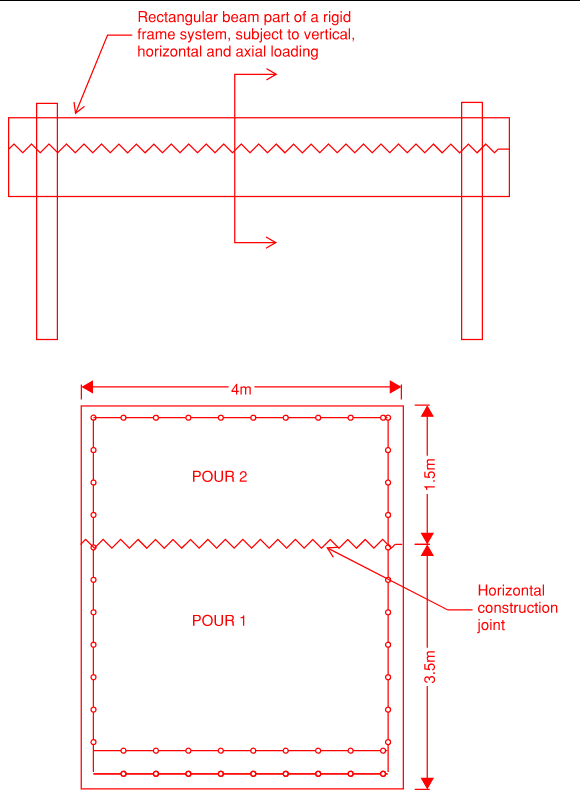
I have a large solid box reinforced concrete beam (h = 5m, b = 4m) with a horizontal construction joint 3.5m from the bottom. I am working with a spreadsheet previously set up by someone else that checked the situation referring to Eurocode 2, 6.2.4:
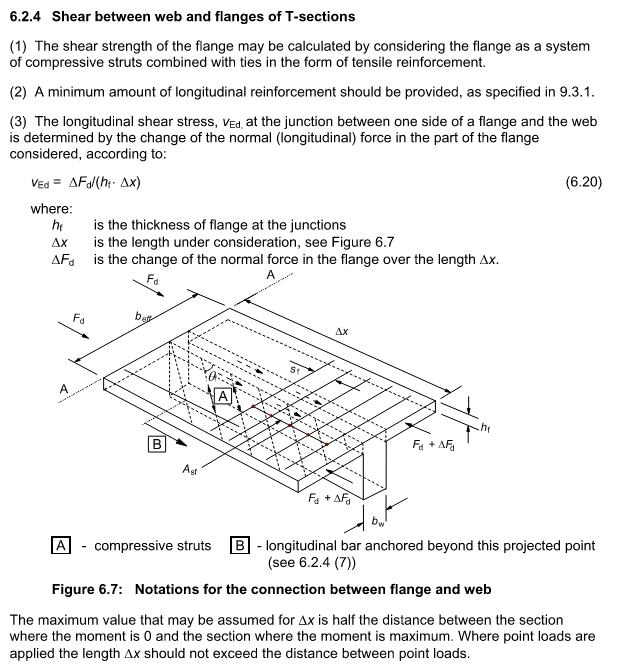
Capture_ue2eo0.png


They calculated q = VQ/I, with V = vertical shear, Q = moment of area of the upper 1.5m of the beam, I = Gross moment of inertia of the full depth concrete beam. They then took vED = q/b to get the shear stress across the joint and compared that to the capacity of VRdi, which comes from 6.2.5:
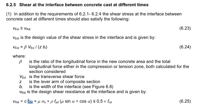
Capture_pbtdnz.png


My first issue is it doesn't seem to make sense to refer to 6.2.4 at all, and this whole thing would be most appropriately covered just following 6.2.5. Would be interested to hear any thoughts on that from those familiar with Eurocode.

Secondly, I'm having a doubt about the calculation of q. I know the theoretical principle but have only every applied it in practice to steel beams. Considering that I am checking ultimate loads and the beam will be cracked, using I = Ig doesn't seem appropriate, but I'm not really sure what is best. Since I want to know the actual shear flow in the concrete on both sides of the joint, it seems weird to use the cracked moment of inertia which disregards the concrete below the NA, which will likely end up above the joint. So I am looking for some advice on what I should consider for I here?

Thirdly, this beam also has a not insignificant and reversible axial force, as well as horizontal transverse shear, which can be applied at any point along the beam's height, which means there can also be torsion. (To be clear, I'm not manually calculating forces in the beam, I already have output from a 3D model with concurrent forces and moments in all three directions at 10th points along the beam). Once I get my shear flow due to vertical transverse shear, do I have to somehow add in axial force, horizontal transverse shear and torsion to get a "total" shear flow across the interface that I would then check against the interface shear capacity? The previous calculation disregarded all of these which seems wrong to me.
 
Replies continue below

Recommended for you

After doing some more reading online, my thought about the third point is that the construction joint should be able to develop a shear transfer for the portion of axial force and transverse horizontal shear that would be taken by the upper portion of the beam (maybe complicated by the fact that all the dead load stresses will be locked into the bottom portion, so only forces from the transient loads would be shared by the full beam cross section).

Since that development should need to happen at the ends of the beam, where longitudinal shear flow is also highest, that would imply that when checking stress across the concrete interface, all three sources should be added together for the worst case?


Dera BridgeEngineer21 (Structural)(OP),

I looked to this thread two times and still i am not sure i got your question.
Having worked with ECs in past , ( now i got retired for several years but responding to the threads just for sharing my experience) , my points ;

- Refer to BS EN 1992-2 clause SECTION 2 Basis of Design, All the clauses of EN 1992-1-1 apply,
- From 2-1-1 Tabel 3.1 obtain fctk, 0,05 for the concrete Strength class,
- Use expression 3.16 ( fctd = αct fctk,0,05 / γC) use the recommended value for αct = 1,0,
- The uncracked shear resistance is calculated with using expression 6.4 which is ,

VRd,c= (I*bw/S ) SQRT (fctd**2 +σcp*α1*fctd )

I hope my respond answers your question.


Use it up, wear it out;
Make it do, or do without.

NEW ENGLAND MAXIM


Hi HTURKAK,

Appreciate the response. I apologize for a long winded question, I probably should have started with the basics. The sketches below hopefully make the situation more clear. I have no questions about the shear design of the beam, my question is just concerning horizontal interface shear across the horizontal construction joint.

Capture_pieojr.png


The questions can be simplified as:

1. Should the capacity of this horizontal joint be taken as expression 6.25 (as copied in my first point)
2. What is the demand on this joint?
a. I know horizontal shear flow is definitely a component of demand. How is it calculated for a cracked concrete beam - with what moment of inertia?​
b. The beam also experiences axial force, transverse horizontal shear, and torsion. Should any or all of those factor into the demand?​
 
Australian not euro but have some answers. Use 6.2.5 with z lever arm for cracked section. You don't need Q & I to calc the stress. 6.2.4 is new to me. We just use our version of 6.2.5 with friction coefficients for monolithic pour when there's no cold joint. 6.2.4 and 6.2.5 seem disconnected because 6.2.4 is strut & tie with stress averaged but 6.2.5 is emoirical with peak stress used.

Do you have more reo than your sketch? Too far apart so ignore the reo because it's doing nothing for the stress in the middle. For axial and torsion you need to do first principles. Free body diagram of the left half above the joint. Needs to be half because the torsion will cancel on the right hand side so you miss the peak where torsion adds to shear stress. Axial won't increase the horiz shear if the force acts evenly on the cross section but would locally if it's concentrated and has to spread out.
 
I thought expression 6.24 as written is geared towards a vertical construction joint? How does vertical shear divided by vertical lever arm result in horizontal shear flow? It doesn't even account for where the construction joint is located in that case. Also not sure I really understand what the beta factor in that equation is.

I agree I'd rather forget about section 6.2.4 since it doesn't seem to apply to this case

This is just a rough sketch, the beam is heavily reinforced (3 rows x 27 Ø32mm bars on bottom and 2 rows on bottom, Ø32 bars spaced at 150mm along the sides, 6 legs Ø20 shear stirrups). Does that still seem like too little reinforcement to count on?

I follow what you're saying about torsion. For axial, the force can be introduced as a concentrated load at the top or bottom of the beam at the ends, so it does need to spread out.

Now, at the end of all this I will have two components of shear parallel to the construction joint (longitudinal shear flow and axial component) and two components perpendicular and coplanar with the construction joint (torsion and transverse horizontal shear). Would I just convert all these to stresses and add together, ensuring it is below the capacity of expression 6.25?


Hi BridgeEngineer21 (Structural)(OP);

Honestly i could not visualize the beam having dimensions 5.0 m H X 4.0m W. Is this a box section? I will try to reply your questions item by item,


- Yes but this is ( 6.2.5 ) additional requirement to the requirements of 6.2.1- 6.2.4 . The capacity is calculated with the expression (6.25)


In this case you do not need to calculate the MOI.The design value of the shear stress in the interface is calculated with the expression (6.24) that is , vEdi = β VEd / (z bi). If the section experiences torsion, it will not be additive for shear at the horizontal interface between concrete cast at different times . If the section is box girder, the torsional shear and vertical shear can be summed for each wall.


Use it up, wear it out;
Make it do, or do without.

NEW ENGLAND MAXIM


HTURKAK, thanks for the response. Yes the section is a box section - I added a sketch to one of my previous posts.

I see that the consensus is now that I should use expression 6.24. I'm very new to Eurocode, so I don't doubt you guys are correct. But I still am having a hard time wrapping my head around it. My doubt is this - The equation doesn't account for the location or even orientation of the construction joint, so using that equation would give me the same shear stress regardless whether my joint is horizontal or vertical, and regardless at what level along the beam's depth the horizontal joint is located. How can that be correct?
 
could you simplify the solution for yourself?
what is AsFy that you are using for the beam flexural strength? That should be developed along the length of the interface from the point of minimum to maximum moment.
this is a simplification that would sort of average out the shear flow, similar to what you would do for composite beam design.
make sure you have enough depth to develop hooked bars above and below the horizontal joint
I don't know eurocode so no comment.
 
There are several ways to deal with shear flow in concrete. If you want well documented methods, look into topper slabs and similar types of precasting. Realistically, even if you didn't have bar between your pours you'd likely be fine as long as your interface is reasonably rough and your load is applied in a way that causes some amount of friction. This may not meet the letter of code, but testing of multi-pour beam and slab systems shows stuff working with pretty much minimal prep.

If you have stirrups or similar, you're basically going to be a-ok by inspection. That being said, I'm used to thinking about rectangular sections, and a box or flanged section is going to be worse if you're doing the joint in the webs, so my gut is maybe not correct in this case. So the math is probably important.

Basically your shear friction design is there to make sure the appropriate longitudinal forces can develop between the two halves of your beam. The way to picture this is that your flange compression or tension forces need to get through your interface. Once the tension/compression couple is in the flange sections, there's no shear in this interface, so it's just the change in moment that matters. Shear is the rate of change of moment, so represents the instantaneous change in a given portion of the beam in terms of kN*m/m or whatever units you want to use. The shear flow equation makes a lot more sense when you think of the beam shear term as an expression of moment change. You can then go to first principles to figure out what the longitudinal shear in the beam is by working out the compression or tension above the point in terms of axial kN/m.

There are a bunch of ways this is done in practice and they all seem to work.

Some methods seems to just take the peak moment, figure out the force above the interface for that moment and then divide that shear along the whole length. They basically ignore the instantaneous change in moment and average it all out across the length of the member with the presumable assumption that internal forces will develop inside the two beam halves to balance everything out. The classical shear flow equation looks at the instantaneous shear at a given point and designs for that, but you have to decide what the force above the junction is. It likely depends on your system as to whether cracked or uncracked moment of inertia is more conservative, or whether there's a simplifying assumption that works.

There are also several code and industry forumulas that simplify things. Some assume various things about the moment of inertia, some assume the point of interest is at the extreme beam fibre, which is conservative. They all generally get back to shear flow somehow.

Basically, there are a boatload of detailed ways that people do this, they can vary by like 50%, but they all seem to work okay.

6.24 is one of these simplifying formulas. It doesn't quite match your situation, though. You'd need to play with the definition a bit to make if fit your situation. If you do that with the change in force in the section above your point of interest instead of the change in force in the flange you're generally okay. This is just shear flow.

I don't think torsion and longitudinal shear flow should heavily interact in a concrete beam, but I haven't thought heavily about box girders which would definitely be the most likely to have peaks interact, so I'm not going to say definitively without a bit more though.
 
Is it a box (hollow) section or solid rectangle?


"I thought expression 6.24 as written is geared towards a vertical construction joint?"

Can be either vert or horiz joint. Just use the shear in the right direction.


"How does vertical shear divided by vertical lever arm result in horizontal shear flow?"

See image. Moments about O at the reo give V * (delta L) = z * (delta C). dC/dL = shear flow = V/z.


" It doesn't even account for where the construction joint is located in that case. Also not sure I really understand what the beta factor in that equation is."

You actually answered your own question. Beta is when the joint is in the compression block. Say exactly halfway down the block then only half of (delta C) is above the joint so the shear flow on the joint is 0.5 * V/z. This is how we use this equation for the flange situation that eurocode uses 6.2.4 for. Use beta = flange area / total compression area.


"two components perpendicular and coplanar with the construction joint (torsion and transverse horizontal shear)"

I think you need to use space truss model for torsion to get the diagonal strut force then convert to longitudinal shear and add to the longitudinal shear due to regular shear/bending. Maybe can use whatever equation eurocode has for the longitudinal torsion reo because that's basically the same as (delta C) due to bending.

 
 https://files.engineering.com/getfile.aspx?folder=0e5dfeb1-d0d4-4aa3-b490-9ab6267aa400&file=shear_flow.jpg

-The shear strength of vertical interface between concrete cast at different times is calculated with expression (6.25) with multiplying with web area.
- The CJ shall be roughened ,indented , etc
- Make sure that the shear strength of the section greater than the flexural to avoid brittle failure .

My opinion..


Use it up, wear it out;
Make it do, or do without.

NEW ENGLAND MAXIM


Thanks all for the great responses. Smoulder's reply is the one in particular that go this through my head and I understand the application of 6.24 now.

I apologize, I realize I've been using confusing terminology. The section is a solid rectangle, not a hollow box.

I do still have a question about this part of Smoulder's post:

"I thought expression 6.24 as written is geared towards a vertical construction joint?"

Can be either vert or horiz joint. Just use the shear in the right direction.​

I now understand that for a horizontal construction joint, which is what my original question was about, vertical shear is what should be used in that equation. However, I'm thinking for a vertical construction joint, I should still use vertical shear. V/bz with beta = 1 would essentially give shear stress across a vertical plane which is what needs to be checked in that case. Is this correct? And if so what is meant by "just use shear in the right direction" then, if shear would be in the same direction in both cases?
 
Another doubt I have about the shear flow: While I follow how we get to dC/dL = V/z, shouldn't it then follow that VQ/I = V/z and therefore I/Q = z? With Q taken for the compression block (since the beta factor in equation 6.24 adjusts for the exact vertical location).

I tried a simple test of this, an unreinforced beam of dimensions b by h. Say the compression block is depth h/3, and lever arm z = h/2. I = bh^3 / 12 and Q = b(h/3)(h/3) = bh^2 / 9. This gives I/Q = 3h/4 ≠ h/2

Can anyone see what's going wrong with my thinking here?
 
Imagine if you will, a tiny square, with a unit force up on the left side and a matching force down on the right (vertical shear). In order to maintain equilibrium, you have to apply the same magnitude forces to left on the top and to the right on the bottom (horizontal shear).

In order to maintain internal equilibrium, at any particular point within the beam, vertical shear = horizontal shear.
 
Thank you BridgeSmith. Yes, I understand that concept. I'm now trying to understand the connecting logic that makes the shear flow equation I'm used to (VQ/I) equivalent to EC 6.24 (V/z). Can you see what I'm missing in my attempted derivation above?
 
Can you see what I'm missing in my attempted derivation above?

I'm not familiar with the Eurocode, only AASHTO. AASHTO uses VQ/I. Anyway, if you're assuming and unreinforced beam, the depth of the compression block should be h/2.

Edit: Assuming z is the distance from centroid of the compression block to the neutral axis, I/Q = h/4 = z.


That was my first thought, but wouldn't that imply that concrete compressive and tensile strength is equal? I don't think that's correct, even below rupture, no?

Regardless, the derivation doesn't work even if I take h/2 for the stress block depth. That results in I/Q = 2h/3.

Anyway, my question is no longer really about Eurocode but about fundamentals. The derivation that Smoulder wrote above for shear flow = V/z makes sense based on fundamentals. But I can't feel confident I understand this when I can't see how V/z and VQ/I can both result in shear flow without being equivalent values.
 
As I said, I'm not familiar with the Eurocode, so I don't know what "z" is. You are correct about I/Q = 2h/3 though.
 
Status
Not open for further replies.

Part and Inventory Search

Sponsor