Continue to Site

Eng-Tips is the largest engineering community on the Internet

Intelligent Work Forums for Engineering Professionals

  • Congratulations waross on being selected by the Eng-Tips community for having the most helpful posts in the forums last week. Way to Go!

Jacobian definitions

Status
Not open for further replies.

BioMes

Bioengineer
Nov 2, 2022
40
Hello everyone!

I’ve seen the following forum thread:
but I still have some doubts regarding this quality measure.

1) Most importantly, I can’t find a single universal definition. Even ranges seem to vary a lot depending on the software. Usually, the range is given as 0 to 1 with 1 being the perfect shape but, as we know, negative values are also possible and indicate inverted elements. So shouldn’t the range actually be -1 to 1 or does it depend on the software too? The aforementioned forum thread also gives two ranges. In some software (like SolidWorks Simulation) much higher positive values are possible. Is it really the case that Jacobian can be defined so differently? Shouldn’t this measure be more unified like aspect ratio?

2) My second doubt is about element types for which Jacobian makes sense as a quality measure. I know that it mostly applies to second-order triangles and terahedra but are all the other element types (like linear triangle and tet and linear/quadratic hex) also verified with this criterion? The linked thread mentions that linear triangle and tet elements always have a Jacobian value of 1 (so it can’t indicate their distortion) but is it really the case regardless of the definition? What about hex elements?
 
Replies continue below

Recommended for you

1) you'd need to read the SW help to find their definition.
2) if the problem is linear I frankly doubt, but do not know, that the ratio only applies to certain element types. It's a matrix property really. Turning linear elements into matrices is a procedural issue, not a fundamental difference in approach. There again I ignored FE theory at uni on the advice of my supervisor.

Cheers

Greg Locock


New here? Try reading these, they might help FAQ731-376
 
It’s not just about SolidWorks Simulation and they don’t share the details about the implementation. The description is here:
The most important parts:

The Jacobian ratio of an element increases as the curvature of the element edges increases to map a curved geometry. […] A good quality mesh has a Jacobian ratio between 1 and 10 for the majority of its elements (90% and above).

So it can be much higher than 1 but they don’t explain why. Thus, I wonder why it’s 0 to 1 or -1 to 1 in some software and no upper limit in other software.

How is it defined in the software you are using?
 
maybe the 0 to 1 range is for actual/ideal (as a ratio).
maybe SW use ideal/actual so their range is (ideally) 1 to infinity but practically they say anything over 10 is really unacceptable (unusable) ?

The ideal shape for a quad is a square, and for a TET it'd be an equilateral tet. The ideal shape for higher order elements would be to have the mid-side nodes at the mid-point of the side (and straight sides).

"Hoffen wir mal, dass alles gut geht !"
General Paulus, Nov 1942, outside Stalingrad after the launch of Operation Uranus.
 
I haven’t found any details regarding the way it’s calculated in SW. Only that values up to 40 are acceptable.

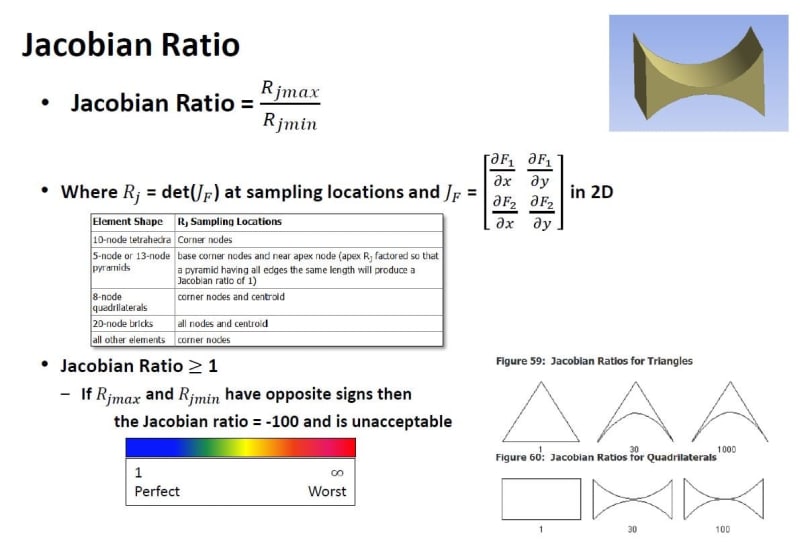
However, Ansys also uses Jacobian ratio >= 1. They define it this way (from the "ANSYS Meshing Advanced Techniques" presentation):

IMG_6115_ohk9qh.jpg


Here’s more detailed description from Ansys:
I’m not sure if it’s the same definition as in SW but it seems to be quite likely.
 
In Finite Element Analysis, each element is a transformed (stretched, warped, rotated, etc.) basic element such as rectangles and triangles. The Jacobian of the transformation determines how the transformation is performed at each point. The Jacobian determinant gives the (oriented) ratio of n-volumes between after and before the transformation. For 2D element (n = 2), 2-volume is simply the surface area.

In most application, the Jacobian determinant is a function of position. In other words, some regions of the element may have larger area after the transformation while other regions may have smaller area after the transformation. The Jacobian ratio is the ratio between the largest and smallest area ratio. As you can imagine, a large ratio means the element is distorted because some regions of the element's area increase much more than the some other regions after transformation. This quality measure is valid and applicable for all types of elements because the meaning of the Jacobian, Jacobian determinant, and Jacobian ratio are the same.

Regarding value range, I think SolidWorks define the ratio as |R[sub]j, min[/sub]| / |R[sub]j, max[/sub]|, which will limit the value to (0,1]
 
Why are you, for lack of a better term, "hung up" on element quality metrics? What are ultimately hoping to achieve? I am asking because, in general, as you refine elements or as deformation occurs, the element quality will change.

*********************************************************
Are you new to this forum? If so, please read these FAQs:

 
rezhadrian said:
Regarding value range, I think SolidWorks define the ratio as |Rj, min| / |Rj, max|, which will limit the value to (0,1]

I think it’s the opposite. SolidWorks and Ansys don’t have the upper limit so they should be both using R_j, max / R_j, min right ?

@IceBreakerSours: I just want to better understand this commonly used measure. Of course, there are also other ways to check and ensure proper mesh quality but it’s good to know the basic quantities in this field.
 
It is used to express shape functions (defined in global coordinates) in terms of natural coordinates - with which matrix and vector entries are evaluated - and to make the change of variables in the integrals, i.e., perform a scaling, e.g., dA = dx*dy = dEta*dNy*det(J).

If aspect ratio of an element is far from unity (e.g. acute angles in a quad), the Jacobian (partial derivatives of shape functions (expressed with node locations and the shape functions in natural coordinates) w.r.t the natural coordinates) becomes large or small, which in turn causes the scaling factor det(J) to become poor (far from unity). The result is poor accuracy in evaluation of matrices and vectors which may cause an ill-conditioned global equation system and therefore poor solution accuracy.

This is my understanding. A mesh that "looks good" is probably also a mesh not plagued by issues with the Jacobian - as you would find out by making "good looking" meshes in commercial software and observing that Jacobian ratios are then rarely flagged.
 
Status
Not open for further replies.

Part and Inventory Search

Sponsor