Eng-Tips is the largest engineering community on the Internet

Intelligent Work Forums for Engineering Professionals

3-2-1 method for cylindrical pressure vessel 1

Status
Not open for further replies.

BioMes

Bioengineer
Nov 2, 2022
40
0
0
PL
Hello everyone!

I’ve read some articles about the 3-2-1 method, like this one:
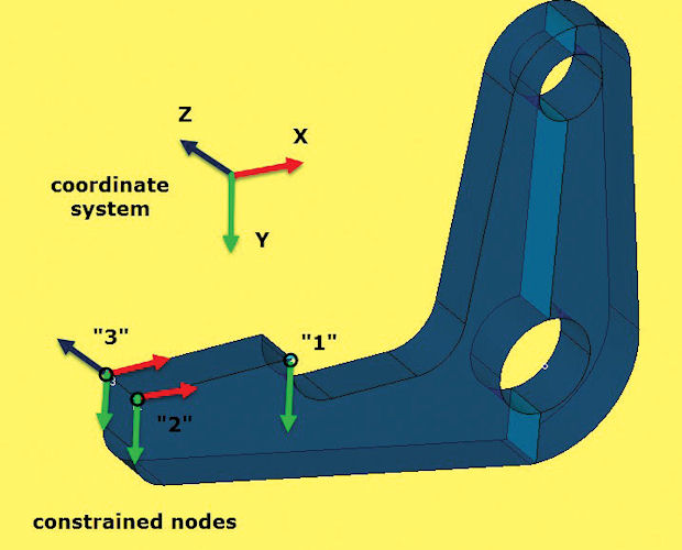
However, I wonder how to use this approach for a simple pressure vessel analysis.

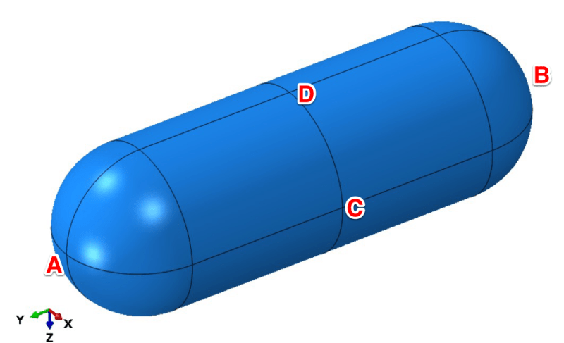
Consider cylindrical pressure vessel meshed with solid elements. It’s symmetric and loaded with internal pressure but let’s forget about symmetry and use only the 3-2-1 method here. This is just an example to understand it better, not a real case study.
IMG_6308_cvtwgv.png


Which 3 points would you select if you were to use the 3-2-1 method for this model?

My idea is to select:
- A as the first point (constrained in 3 directions: X, Y and Z)
- B as the second point (2 directions fixed: X and Z)
- C as the third point (fixed only in the Z direction)

I also marked point D as an alternative to point C. It could be constrained in the X direction to prevent the same rigid body motion (rotation about the axis of the vessel).

However, I’m not sure if this approach is a good idea. What do you think about it? Would you do it differently? If yes, how?
 
Replies continue below

Recommended for you

any set should work fine ... the model should have pretty uniform stiffness.
One thing I found is that results can vary depending on how you build the geometry ... so I'd build a tube, put pressure on, and see it inflate as it should.
Good thing models are too dumb not to realise there is no end cap !

"Hoffen wir mal, dass alles gut geht !"
General Paulus, Nov 1942, outside Stalingrad after the launch of Operation Uranus.
 
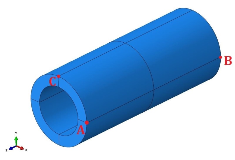
Thanks. Speaking about a pipe with an internal pressure, there are no nodes in the middle to fix so what do you think about the approach below?

IMG_6319_uvhihy.jpg


A: X=Y=Z=0
B: X=Y=0
C: X=0 or Y=0

Notice that the axis are different now. Does if make sense or would you do it differently?
 
we're just taking out rigid body motion. the three point define a plane that the part moves relative to. That is the test for the three points, that and ensuring that none of your six constraints are co-linear.

"Hoffen wir mal, dass alles gut geht !"
General Paulus, Nov 1942, outside Stalingrad after the launch of Operation Uranus.
 
yeah ... the constraints need to be orthogonal with the plane ... or do they ?

with C opposite A, Cy and Ay react Mz
but Mx is reacted by Ay, By, and Cy ... but we don't call that over-constraint ?

Ax, Ay, Az react the three forces Fx, Fy, Fz
Ay and By (and Cy) react Mx
Ax and Bx react My
Ay and Cy (and By) react Mz

with C at 90 degrees, C can be either x or y to react Mz (with Ax or Ay) and whichever it is, this will also react My or Mx.

no?

try it ... if it doens't work then constraints need to be orthogonal to the rigid plane.

I can see that it may be better practice to keep the plane orthogonal, 'cause I can ualise examples where being at an angle (to the global freedoms) would be a problem.

"Hoffen wir mal, dass alles gut geht !"
General Paulus, Nov 1942, outside Stalingrad after the launch of Operation Uranus.
 
The purpose of the constraint at C is to fix rotation about a line thru A-B.
But if C is where shown, and X=0, there is X=0 at all 3 points, but those constraints must be in a plane parallel to the y-z plane, but they are not. Similarly if Y=0 at C.
 
yes, I agree with you. The plane made by the three points needs to be orthogonal to the freedoms being constrained ... if global freedoms (are being constrained) this means a plane oriented in the global axes (like C opposite A).

with C as drawn plane ABC is not aligned to the global axes. So when we constrain C in x, we are constraining in both x and y of the plane ABC, and so constraining AC which is over-sonstraining.

If you set up a local co-ord system plane ABC, and constrained those freedoms, then it'd be ok (but a lot more work !).

It's good to think about these things.

"Hoffen wir mal, dass alles gut geht !"
General Paulus, Nov 1942, outside Stalingrad after the launch of Operation Uranus.
 
If you’re modelling a pipe with internal pressure, due to symmetry you can model just 1/4 of it. The three surfaces can then be restrained appropriately. Just for info, thin walled cylinder theory can also model a pipe. Ah, 3-2-1!
 
I’ve tried both locations of C (original and suggested by SWC) and they give the same results with zero reaction forces at the supports.

Sure, symmetry would normally be used here but the idea here is to forget about it and focus only on the 3-2-1 method. Sometimes symmetry can’t be used like when buckling is involved.
 
I've always used the philosophy that if the structure has symmetry, the 3-2-1 restraints should be symmetric as well. That way, when a symmetric load case is applied (e.g. internal pressure in a pipe or vessel), the displacements will also be symmetric. This doesn't affect the accuracy of the stress / strain results, but it can make visualisation of the deformation behaviour more intuitive.

In BioMes' original post, the vessel would appear to be anchored at A, and grow in the negative Z direction at B, C, and D when subject to internal pressure. A more intuitive behaviour would be to fix Z at C or D rather than A. When subject to internal pressure, the pipe in the post of 3 Feb 17:41 would appear to grow in the negative X, Y and Z directions, whereas a more intuitive behaviour would have it grow about its centre of mass. With a little thought, you can set up 3-2-1 restraint sets which will emulate this behaviour.

Of course, using Boundary Conditions of symmetry to create a 1/2, 1/4 or 1/8 model is more computationally efficient.

 
Does the cylinder expand under the pressure load? If you're getting zero reaction force at point C, that point must be moving in the -X direction and the cylinder is rotating about A-B (for a Y=0 constraint there) to allow for the expansion. I would be interested in seeing X and Y displacement contours of the end of the cylinder. Maybe that rotation doesn't matter, but it's still and odd thing to see in an analysis.
 
@jhardy1

Right, it can be confusing. The axes are different because of the way those parts were modeled (vessel was revolved, pipe was extruded). But let’s keep those axes to avoid even more confusion. I’ll just try to make it clear which orientation I’m talking about each time.

If I understand your suggestion correctly, I should fix those points in the vessel case:
- A: X, Z
- B: X, Z
- C: Y, Z

It works - reactions are zero and the vessel seems to be expanding from its COG. The only problem is that it’s not a 3-2-1 method per se but it’s a great way to constrain the model anyway.

However, I can’t figure out how to apply this approach to the pipe model since there I don’t have the nodes in the middle (on the axis of symmetry - Z).
 
we've been talking about constraining rigid body motion. 1-2-3 is good for this.

if you want to constrain the face, then that is different. you could say ...
1) "I want to fix this face" (and constrain each node out-of-plane), or
2) "I want plane sections to remain plane" (then define the plane and constrain the nodes to this plane, and not the global freedom).

"Hoffen wir mal, dass alles gut geht !"
General Paulus, Nov 1942, outside Stalingrad after the launch of Operation Uranus.
 
@SWComposites: I’ve done this already and it’s working properly but jhardy1 mentioned a different approach where the pipe expands from its center of mass which is more natural so I want to give it a try. I don’t know how to achieve that though.
 
I guess that is an interesting question. My understanding (flawed as it is) is that we're taking out rigid body motion, and if we do this properly it has no impact on the model results. I don't think your 3-2-1 constraints over constrain the pipe (from breathing as it should).

One way to check would be to take out rigid body motion by constraining all 6 dof at a node. Now you can't do this on a solid model, but you can on a shell model.

"Hoffen wir mal, dass alles gut geht !"
General Paulus, Nov 1942, outside Stalingrad after the launch of Operation Uranus.
 
Status
Not open for further replies.
Back
Top