Hello everyone!
I’ve read some articles about the 3-2-1 method, like this one:
 www.digitalengineering247.com
However, I wonder how to use this approach for a simple pressure vessel analysis.
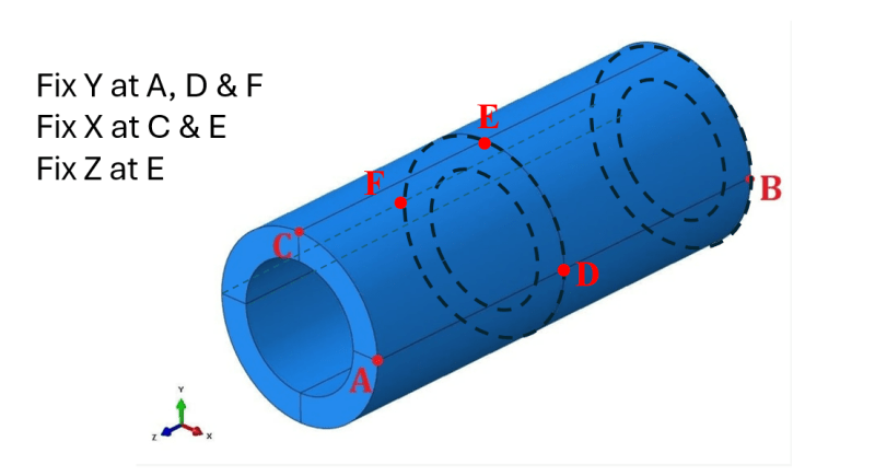
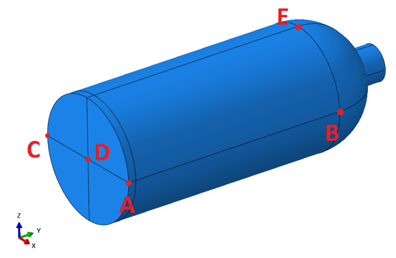
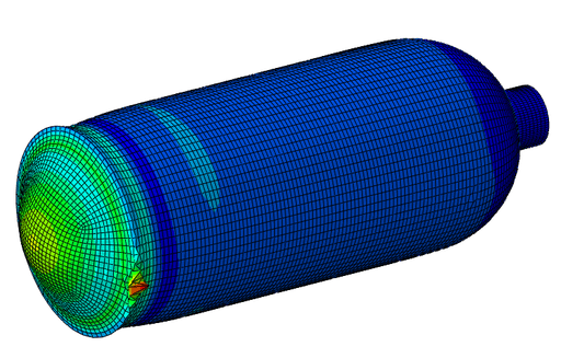
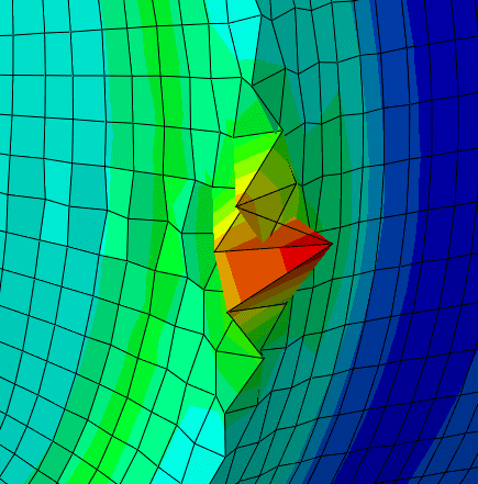
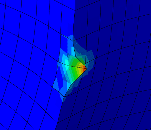
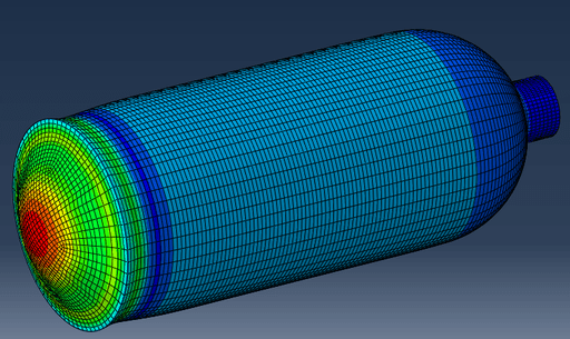
Consider cylindrical pressure vessel meshed with solid elements. It’s symmetric and loaded with internal pressure but let’s forget about symmetry and use only the 3-2-1 method here. This is just an example to understand it better, not a real case study.
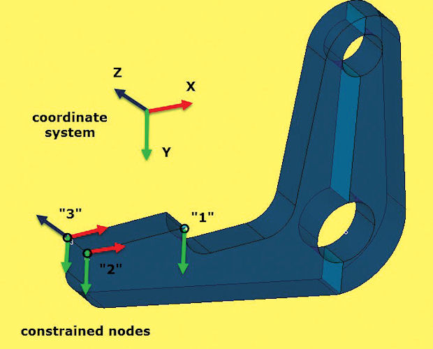
Which 3 points would you select if you were to use the 3-2-1 method for this model?
My idea is to select:
- A as the first point (constrained in 3 directions: X, Y and Z)
- B as the second point (2 directions fixed: X and Z)
- C as the third point (fixed only in the Z direction)
I also marked point D as an alternative to point C. It could be constrained in the X direction to prevent the same rigid body motion (rotation about the axis of the vessel).
However, I’m not sure if this approach is a good idea. What do you think about it? Would you do it differently? If yes, how?
I’ve read some articles about the 3-2-1 method, like this one:
Free-Floating FEA Models - Digital Engineering
Apply equivalent pressure distributions on a structure without needing direct constraint boundary modeling with the 3-2-1 method..
www.digitalengineering247.com
However, I wonder how to use this approach for a simple pressure vessel analysis.
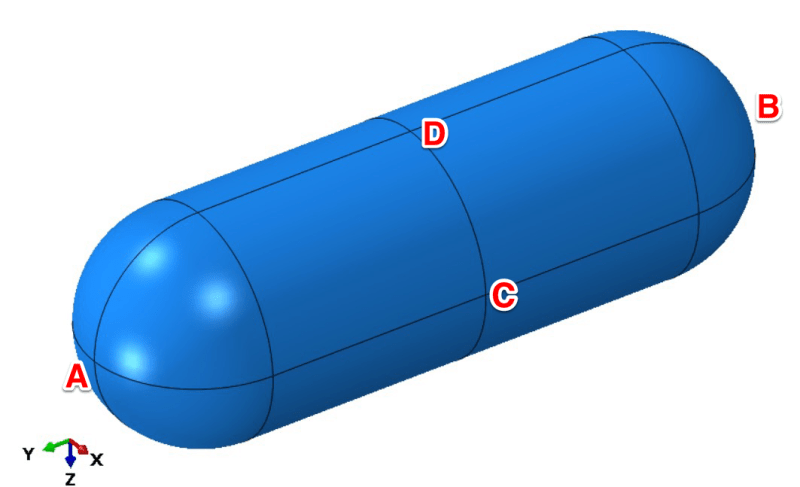
Consider cylindrical pressure vessel meshed with solid elements. It’s symmetric and loaded with internal pressure but let’s forget about symmetry and use only the 3-2-1 method here. This is just an example to understand it better, not a real case study.
Which 3 points would you select if you were to use the 3-2-1 method for this model?
My idea is to select:
- A as the first point (constrained in 3 directions: X, Y and Z)
- B as the second point (2 directions fixed: X and Z)
- C as the third point (fixed only in the Z direction)
I also marked point D as an alternative to point C. It could be constrained in the X direction to prevent the same rigid body motion (rotation about the axis of the vessel).
However, I’m not sure if this approach is a good idea. What do you think about it? Would you do it differently? If yes, how?