Continue to Site

Eng-Tips is the largest engineering community on the Internet

Intelligent Work Forums for Engineering Professionals

  • Congratulations waross on being selected by the Eng-Tips community for having the most helpful posts in the forums last week. Way to Go!

3-2-1 method for cylindrical pressure vessel 1

Status
Not open for further replies.

BioMes

Bioengineer
Nov 2, 2022
40
Hello everyone!

I’ve read some articles about the 3-2-1 method, like this one:
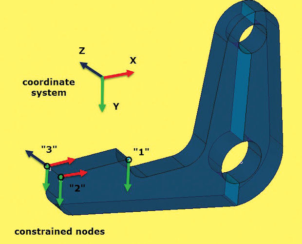
However, I wonder how to use this approach for a simple pressure vessel analysis.

Consider cylindrical pressure vessel meshed with solid elements. It’s symmetric and loaded with internal pressure but let’s forget about symmetry and use only the 3-2-1 method here. This is just an example to understand it better, not a real case study.
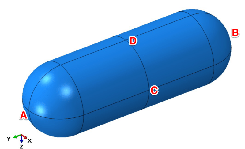
IMG_6308_cvtwgv.png


Which 3 points would you select if you were to use the 3-2-1 method for this model?

My idea is to select:
- A as the first point (constrained in 3 directions: X, Y and Z)
- B as the second point (2 directions fixed: X and Z)
- C as the third point (fixed only in the Z direction)

I also marked point D as an alternative to point C. It could be constrained in the X direction to prevent the same rigid body motion (rotation about the axis of the vessel).

However, I’m not sure if this approach is a good idea. What do you think about it? Would you do it differently? If yes, how?
 
Replies continue below

Recommended for you

@BioMes:

You said "The only problem is that it’s not a 3-2-1 method per se but it’s a great way to constrain the model anyway."

I don't understand why you don't think it's a valid 3-2-1 restraint set? You've restrained 3 x Z, 2 x X and 1 x Y; the vessel is restrained against free body motion, but not over-restrained, so it is free to "breathe", and the reactions at the restraints will all be zero when a self-equilibrating load set such as internal pressure is applied.

 
@BioMes:

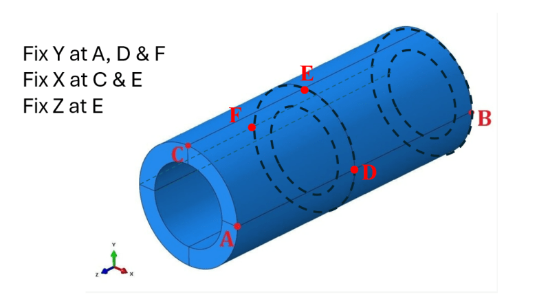
Here's one way of restraining the pipe model so it will "breathe" about its center of mass:

Define three new nodes D, E & F at the midplane, being the +X, +Y and -X points of the outside diameter respectively. Then Fix Y at A, D & F, fix X at C & E, and fix Z at E. There are many variants of this arrangement you could employ.

3-2-1_Restraint_for_Pipe_uxaizf.png


I don't think you need to define mid-thickness nodes.

why not have X at A & D ? why is C & E "better" ?
why not have Z at A ?

As long as there are zero reactions at whatever set of nodes you use, there all is "good" ... no?

"Hoffen wir mal, dass alles gut geht !"
General Paulus, Nov 1942, outside Stalingrad after the launch of Operation Uranus.
 
I'm not defining any mid-thickness nodes - I merely modified BioRes' original restraint set-up for the open-ended pipe. The suggested restraints would work equally well on a mesh of plate / shell elements, or solid elements, or whatever.

Yes, any set of 6 restrained DOF which prevent free body motion, without over-constraining, are equally "good" as far as stress and strain results are concerned.

As per my post of 13:25 on 4 February, I have always preferred to use constraint sets which are symmetric around the centre of mass of a symmetric model, if possible, so that the model will expand and contract symmetrically about the centre of mass when subjected to a symmetric self-equilibrating load set. BioRes could not see how to do this when there are no nodes on the axis of the model, so I offered one solution.

This is purely as an aid to visualisation of the deformed geometry, it doesn't affect the solution accuracy - but I find it easier to interpret +1 mmm on the +X side and -1 mm on the -X side as showing 1 mm radial growth, whereas 0 mm on the +X side and -2 mm on the -X side needs a little bit of mental gymnastics to understand the deformation magnitudes and shapes.

If you restrain X at A & D, the model will grow in the -X direction when internal pressure is applied, rather than expanding symmetrically about the pipe axis. If you restrain Z at A instead of D, the pipe will grow in the -Z direction, rather than expanding equally at both ends.

 
I see your point, just something I've never been bothered about.

"Hoffen wir mal, dass alles gut geht !"
General Paulus, Nov 1942, outside Stalingrad after the launch of Operation Uranus.
 
Hi,

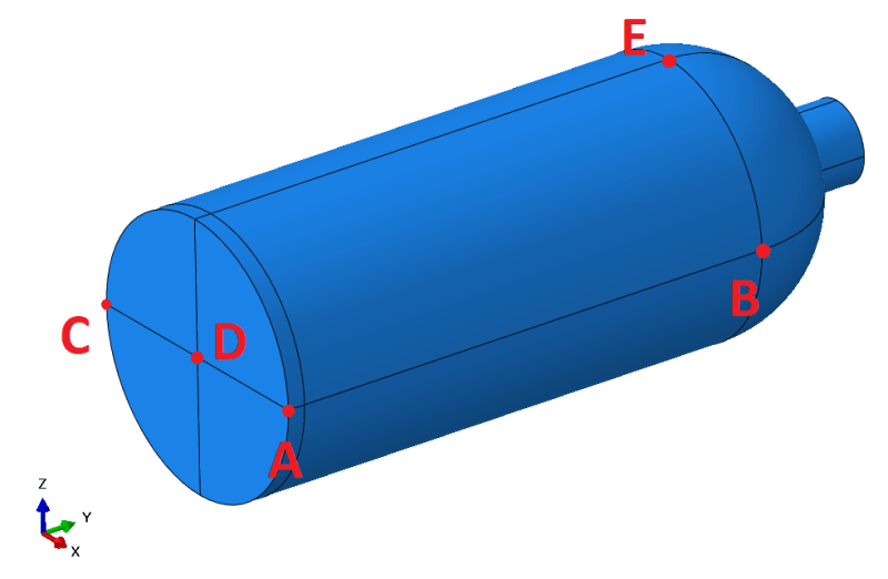
I’m working on the last example - scuba tank mentioned in the referenced article. Here’s the model (of course, it’s hollow inside and has internal pressure applied)

IMG_6570_z2gxxi.png


I tried using the same approach as for the pipe:
A: X=Y=Z=0
B: X=Z=0
C: Z=0

(notice different axis orientation, additional point marks are for reference if needed)

But it didn’t work - I got stress concentrations (at A) and non-zero reaction forces.

This example is something between the vessel and pipe but it’s also not symmetric in one plane and has one hollow end. How should I constrain it using the 3-2-1 method?
 
1) sometimes it's the way you built the geometry. I've seen it (done it) myself ... different ways of creating the fuselage geometry have different results. yes, nuts !?

2) if you have 6 dof as defined, then you should have zero reactions. Are you SURE there are no other constraints ? no "AUTOSPC" ??

3) I'd build just the constant section, run this, check that it inflates as it should, check the hoop stress is what it should be.

oh, just reread ... if you have an opening at one end (where the regulator valve would be) and pressure on all the other faces, then you have an imbalance in load, and this will appear at the constraints ... you should be able to figure out what the reactions should be ... some X load (= p*A) and some Y couple.

"Hoffen wir mal, dass alles gut geht !"
General Paulus, Nov 1942, outside Stalingrad after the launch of Operation Uranus.
 
show a plot of the deformed geometry (this often can highlight constraint issues).
 
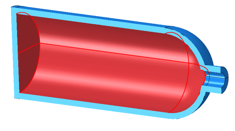
Yes, there’s an opening and the pressure is only applied inside the tank:

IMG_6580_mi8egu.png


Does it mean that the 3-2-1 method can’t be applied here? This case is mentioned in the article about it (there’s no geometry though).

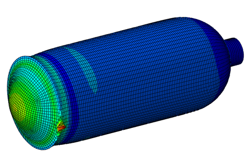
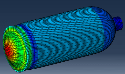
Scaled deformed shape with stress plot (notice what happens at A):

IMG_6579_pxeuqt.png
 
hmmm, very strange deformation. though maybe the flat end plate bowing outward puts moments at the shell interface.
can you zoom in on Pt A?
and are you sure you don't have any moments constrained?
 
yes, deformation is "funky". I guess it is the very low bending stiffness of the shell is causing the funkiness.

your X constraint at A is reacting the load imbalance, and so spiking the local stresses. cover the regulator opening and see what happens.

I think real scuba tanks have a spherical end cap ... a flat end cap is not a good design. Now it could be that the stresses are low enough to accommodate bad design features.

"Hoffen wir mal, dass alles gut geht !"
General Paulus, Nov 1942, outside Stalingrad after the launch of Operation Uranus.
 
I’m using only solid (hexahedral) elements here, no shells.

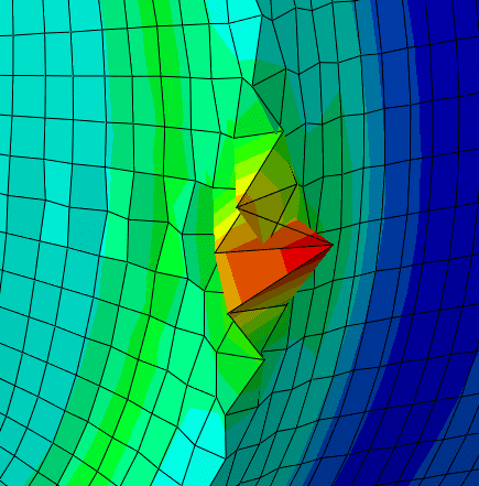
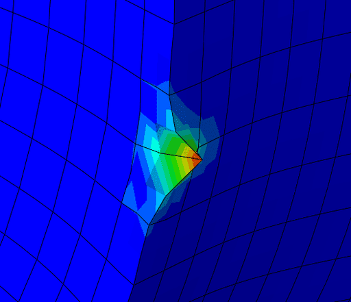
Here’s the close up:

IMG_6582_pffzak.png


It seems to be some hourglassing. With second-order fully integrated hex elements:

IMG_6583_ca0bx7.png


Now if I cover the nozzle:

IMG_6581_kyaozx.png


Does it mean that the 3-2-1 method can’t be used if the scuba tank is open? Or do I need a different set of constraints?

Btw. this is just a simple example to test the method discussed in this thread so I don’t follow the actual design rules for this kind of equipment.
 
"Does it mean that the 3-2-1 method can’t be used if the scuba tank is open?" ... no, it means you have to be careful. If you have an imbalance in load, you have to understand where that is going to be reacted in the real world. If you had this open pressure vessel in the real world, you'd've have a small rocket, or at any rate not a static problem to solve.

"Or do I need a different set of constraints?" ... probably the best way is to cover the exhaust, and all is easy. Next would be to use body force as the reaction, then with a balanced body you cold restrain it however you like (3-2-1 style) ... this at least represents the instant the exhaust is opened. Or, worst, accept this and restrain the body far from the point of interest ... I'd suggest an RBE joining the throat of the exhaust to the CL of the exhaust, then suppress Y there (maybe X and Z too) and carefully constrain the body to take out the other freedoms.

"Hoffen wir mal, dass alles gut geht !"
General Paulus, Nov 1942, outside Stalingrad after the launch of Operation Uranus.
 
You have a slight imbalance in load in the negative Y direction, equal to the internal pressure times the area of the open neck. Effectively, you are anchoring an open "rocket bottle" by two point restraints, so it is not surprising that you have non-zero restraint forces, and local stress concentrations.

Try adding a ring load around the neck of the bottle - this force would be applied by whatever fitting is screwed into the neck of the bottle, and then you will have a full self-equilibrating load set.

 
Jhardy1 got it. In addition to the constraint issue that you have, you also aren't supplying the full load that the tank will see. You're missing the load generated by the pressure on the excluded area. If you aren't concerned about the expansion behavior of the neck area, an easy fix would be to just cap it off so you can apply the pressure to the full inner surface of the tank. Then if you change the pressure you don't have to worry about re-calculating what the missing load will be. You can also minimize the effect of the fictitious plug by making it out of a more compliant material.
 
this was pointed out on the 26th (at 20:00), and, I think, has been incorporated into the model

"Hoffen wir mal, dass alles gut geht !"
General Paulus, Nov 1942, outside Stalingrad after the launch of Operation Uranus.
 
BioMes
Scuba tank is not open. I don`t know exact design and location but scuba tank should have gas reductor/breathe regulator to reduce breathing gas pressure to allowable value. For strength calculations we can neglect pressure after gas reductor (300 bar in tank and like 0.05...0.1 bar after breathe regulator). So for FEA purposes scuba tank closed even when diver breathe (and obviously it is closed when it transported to diving site because it does not leak) but you should somehow represent part of system that is under high pressure.
If you manufacture only tank itself than you can model fittings that connect tank to flexible hose and put an artificial end cap at the edge between metal fitting and flexible hose. It can be flat because you do not interested in stress distribution in metal fitting, it is task for another engineer.
You can find detailed instructions about modeling of pressure vessel flanges and connections in design code for your industry.

As for general principle when you can or can not apply 3-2-1 method - for your case it is result of Gauss-Ostrogradsky theorem (or maybe Stoke`s theorem?) that uniform pressure acting on a closed surface produce zero resultant force and for 3-2-1 method model loads should produce zero resultant force.
 
Status
Not open for further replies.

Part and Inventory Search

Sponsor