Continue to Site

Eng-Tips is the largest engineering community on the Internet

Intelligent Work Forums for Engineering Professionals

  • Congratulations waross on being selected by the Eng-Tips community for having the most helpful posts in the forums last week. Way to Go!

CMAA 74 mandatory for Monorail design? 1

Status
Not open for further replies.

CDLD

Structural
May 20, 2020
217
Quick question for the experts out there.

Are the bottom flange local bending provisions in CMAA 74 mandatory for monorails in the US?
I am referring to the design of S-shapes with trolley hoists, not patented track or enclosed track.

As far as I can tell, there isn't a US spec that covers monorail design, other than the impact factors in ASCE 7-16.

ASME B30.11 "monorails and underhung cranes" points to CMAA 74 (not applicable to monorails), ANSI MH27.1 (applicable only to patented track monorails) and ANSI MH27.2 (applicable only to enclosed track monorails).

 
Replies continue below

Recommended for you

I don't know if mandatory, but good engineering practice... which if far more important, IMHO.

-----*****-----
So strange to see the singularity approaching while the entire planet is rapidly turning into a hellscape. -John Coates

-Dik
 
I do intend to check local flange bending, just not with CMAA equations.

I believe the CMAA equations to be over conservative.

CMAA 74 uses an elastic distribution of wheel loads (which is intended to prevent local plastic deformation of the flange)in combination with factored loads.
 
I use plastic design for steel structures, nearly all the time and have for decades. Monorail crane beams is are not likely a good place to start. There are likely other areas for economy. My $0.03CAN.

-----*****-----
So strange to see the singularity approaching while the entire planet is rapidly turning into a hellscape. -John Coates

-Dik
 
I use elastic design for the runway beam also.

For local flange bending, I think I can use elastic design with serviceability loads and plastic design with factored loads.

Screenshot_2024-02-07_134832_tp8dv9.png
 
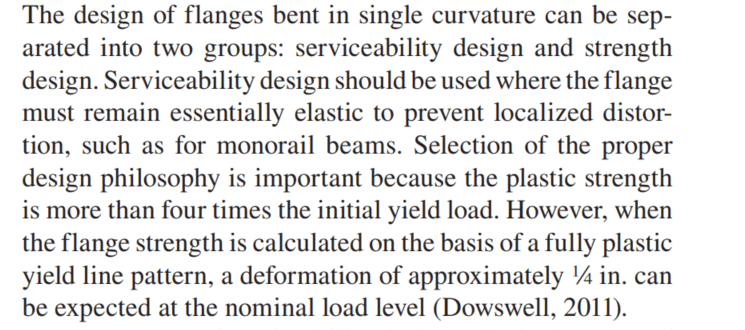
There is a difference between plastic design and plastic capacity. I use the plastic capacity of the flange against factored loads (yield lines from the Dowsell paper) and elastic stresses are checked against service loads (CMAA 74). This is consistent with best practice to my knowledge
 
Where things get complicated is determining LTB behaviour for monororails without rotational restraint at supports and with cantilevers, but that is an entirely different discussion, and using elastic capacities would only provide a false sense of reserve strength here.
 
canwesteng said:
Where things get complicated is determining LTB behaviour for monororails without rotational restraint at supports and with cantilevers, but that is an entirely different discussion, and using elastic capacities would only provide a false sense of reserve strength here.
How do things get more complicated... I only ask because I have a cantilever monorail to support 10T that is about to be installed soon. [ponder]

Monorails are a stabilising load and I generally find that deflection governs for cantilevers. As far as effective lengths go, I find this a good guide.

CDLD said:
I do intend to check local flange bending, just not with CMAA equations.

I believe the CMAA equations to be over conservative.

CMAA 74 uses an elastic distribution of wheel loads (which is intended to prevent local plastic deformation of the flange)in combination with factored loads.

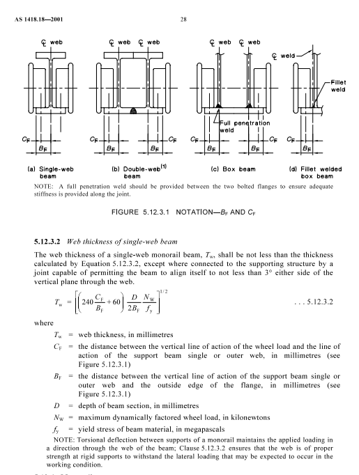
You can try your luck with AS codes and advice on flange design for monorails. I'm not sure if it is more or less conservative.

monorail_t83xk3_bq2gi0.png

monorail2_p76ite_lseylj.png
 
Canwesteng, for a simple span monorail I use the span length as the unbraced length.
This is assuming the supports act as a torsional support which can be validated with appendix 6 in A360 (I've never actually done this for a monorail).
Theoretically, you would need a stocky enough web to prevent distortional buckling, if not I think partial depth stiffeners would do the trick.

canwesteng said:
I use the plastic capacity of the flange against factored loads (yield lines from the Dowsell paper) and elastic stresses are checked against service loads (CMAA 74). This is consistent with best practice to my knowledge

Good to see others using the Doswell paper.
Do you do a biaxial stress interaction for the strength design check?

I'm a little confused by your last statement "elastic stresses are checked against service loads (CMAA 74)".
CMAA 74 uses a reduction factor of 0.6 on the allowable stress.

 
human - I use that reference as well for the cantilever portion. I also bump up the unbraced length a bit for an unstiffened web, based on "Lateral Stability of Beams on Seats" by Bradford and Trahair. Not necessarily complicated, but requires a bit more engineering than just plugging and chugging into formulas.

CDLD - CMAA 74 is not a code requirement and doesn't even apply to monorails (in the exclusions), so I believe you are free to omit the allowable stress reduction. I find it is the best way to determine the elastic stresses in the flange. For an underhung bridge you could argue it is required, and your flange would be beefier as a result.
 
Another thing that's been bothering me is the biaxial stress interaction in CMAA.
In my opinion it is not needed.

David T. Ricker proposed a simple equation in the 1999 Steel Interchange, to check local flange bending with a 45 degree yield line - using elastic strength and factored loads - no Von Mises interaction was mentioned, nor do I think its required.

Let me explain.

In the Doswell paper, it is implied that serviceability loads are recommended for interaction between flange local bending stress and longitudinal normal stress in the beam. The paper also recommends a separate strength design check, but that is not my focus, nor does it ever govern, as the plastic capacity and effective width are greatly increased.

Now lets imagine you are designing a new monorail and it is at 100% capacity for combined bending, torsion, weak-axis bending - your serviceability normal stress in the beam axis would be a max of 30 ksi (0.6*50ksi yield strength)

Now if you do a check for local flange bending with a 45 degree yield line, factored loads, and using elastic strength and also miraculously at 100% of your flange capacity - your serviceability normal stress perpendicular to the beam axis would also be max 30 ksi.

When you interact these stresses with Von Mises you get (30^2+30^2+30*30)^0.5 = 52 ksi
4% overstress from 50 ksi..

You will never have a utilization of 100% on both axes', not to mention the 45 degree yield line is conservative (you can go a little wider and remain elastic as per Doswell paper), and additionally you will have little warping and weak-axis stress at the point of interaction.

In my opinion, the 45 degree yield line proposed by David T. Ricker in 1999 Steel Interchange is adequate in checking local flange bending without the need for any biaxial interaction.

Am I crazy?
 
Human, for cantilevers I use the max between the backspan length and 3 times the overhang length.
I looked quickly at your link and it also recommends three times cantilever length.
 
CDLD - CMAA 74 is not a code requirement and doesn't even apply to monorails (in the exclusions), so I believe you are free to omit the allowable stress reduction. I find it is the best way to determine the elastic stresses in the flange. For an underhung bridge you could argue it is required, and your flange would be beefier as a result.

This is what I was looking for!!!
I think we agree on approach.
Do you still apply the 75% factor when using the CMAA equations (without 0.6 safety factor)
I'm not quite sure why this is there?
Screenshot_2024-02-07_164024_dvfjos.png
 
I use the 75% - there is no explanation for it, but consider that global bending puts the flange in uniform axial tension, and local effects put the flange in local plate bending. If only the extreme fiber of flange starts to yield, I don't think you will observe any deflection in actuality.
 
I worry that the factor is used to lower the safety factor and make it somewhat closer to a serviceability check.
I am just guessing - hard to say, because CMAA gives no explanation!
 
I use the local stress stuff if I'm doing a new design, generally, because it's a good industry standard that is a reasonable reference for what constitutes good practice.

That being said, I agree that they're conservative and possibly overly so. I don't flag existing stuff that I run into as a problem if it doesn't meet those requirements and I've uprated existing railways that failed that check. I've seen legacy items that are significantly overstressed using it as a basis (like, a couple of times over) with no real distress.
In that context I effectively treat it like a serviceability check as long as I've done some other collapse load verification that there isn't a safety issue. In these conditions, though, I also generally have some sort of qualification load test documentation or operational history which helps with confidence.

You'd also have to think about what sort of fatigue conditions the equipment is in, though. I'm generally looking at very low use maintenance cranes. I'd be more concerned at operational cranes getting lots of cycles in high local stress ranges.
 
Good post TLHS, your approach is reasonable in my opinion.
The monorails I deal with are also low use (maybe once a year).
 
Status
Not open for further replies.

Part and Inventory Search

Sponsor