Eng-Tips is the largest engineering community on the Internet

Intelligent Work Forums for Engineering Professionals

  • Congratulations waross on being selected by the Eng-Tips community for having the most helpful posts in the forums last week. Way to Go!

Corner rebar detail 1

Status
Not open for further replies.

JeffG1

Coastal
Feb 14, 2024
2
US
I am sure that I am over thinking this corner detail. The footing has multiple bars,I understand the basic idea to tie the inside bar to the outside bar with L bars doing 90s, i am drawing a blank with how to connect the other 6 bars in the corner.Would u bars work better in this application, or is there not enough room for error/ working in the field with the relatively congested detail.
Screenshot_20240214_081315_Word_i4yjzh.jpg
 
Replies continue below

Recommended for you

Maybe you can provide some clarification. What do you mean by "inside bar" and "outside bar" and why do they need to be tied together? Which bars are you referring to when you say "the other 6 bars in the corner" and what are you wanting to connect them to? Why would what you have shown not leave room for constructability?

On another note, what is this footing supporting? Is it a retaining/screen wall subjected to lateral loading or is it just a strip footing with gravity loads only? If it is a lateral footing and goes into uplift, you may want to consider adding top steel along the 54" dimension. If it is a gravity footing, I don't see why you need the top steel you have shown for such a shallow footing.
 
This is concentrically loaded. You don't need the rebar at the top, or to tie them with the bottom rebar. Are you talking about tying things together in plan? There should be sufficient development length by doing a rebar grid.

Also, that's a lot of rebar for a 12" footing. The longitudinal rebar is generally for shrinkage and cracking, min reinf around 0.0018 if I recall correctly.
 
Why so many longitudinal bars in two layers? Dowel hook is going the right way.

-----*****-----
So strange to see the singularity approaching while the entire planet is rapidly turning into a hellscape. -John Coates

-Dik
 
Joel,

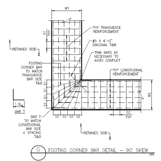
What's the deal with the radial style bars in the intersection? I don't think I've ever seen that detail. I can't quite figure out how that load transfer is working especially with them all terminating in the same spot. How does anchorage on them work and what failure are you preventing.

edit: Oh that's a plan... still don't think I've seen that and not necessarily sure what it's up to but I'm not as completely confused as I was
 
I'd not normally put the #5 diagonal T&B or the 'radial' bars at the re-entrant corner, and I might have 4#5 bottom longitudinal.

-----*****-----
So strange to see the singularity approaching while the entire planet is rapidly turning into a hellscape. -John Coates

-Dik
 
My assumption is that the longitudinal footing bars are just temp & shrinkage bars and thus smaller in size (often #4 bars). They aren't really doing any work and they don't have much capacity.

The transverse bars are working hard transferring the moment at the base of the stem into the supporting ground. I usually hook the bottom of the vertical wall bars and do a longer than normal hook extension so that they can be lapped into the bottom mat of the footing bars. In my mind, I am trying to "wrap the wall moment around the 90 degree corner" down into the footing.

So.....with all that being said. The radial bars at the corner are an attempt to keep all my primary bars in line. If I don't do the radial bars, then I would be sending my wall moment into the small T&S bars.

 
That's a strange-looking cross section. Some thoughts:

- If this footing is just 12" thick, you might not have enough depth to develop your hooked bar.
- If the hooked bar is developed, the bottom bars might not be necessary.
- If you really want or need top bars, provide a few transverse bars to tie the longitudinal bars to.
- If the soil support is more or less even, the myriad of longitudinal bars serve almost no purpose. Especially the top bars.
- Unless there is some large vertical load in the corner, I'd just run the straight bars straight through.
- If there is an overturning force, there may be tension in the top of the footing, but no transverse bars to resolve it.
- Where the drafting is poor (e.g. bars running through bars) one tends to question the engineering behind the detail.
 
Make the hook longer... with #5 bars, there are fewer to place, and likely a tad less expensive. Bottom bars can be used as support bars for the transverse reinforcing.

-----*****-----
So strange to see the singularity approaching while the entire planet is rapidly turning into a hellscape. -John Coates

-Dik
 
I can't believe ya'll don't love my footing detail. I forget the origins of the detail, but it might have been a CRSI manual.

I'm trying to keep the primary footing bars inline with the primary wall bars.

Koot would probably like it if he were here.
 
Borrowing from a comment in another thread, that footing plan at the corner is just 'daft'. Just provide transverse bars with cogs (90 degree hooks) in both orthogonal directions, and run the bottom longitudinal bars straight through. No top bars required.
 
Man, it's a tough crowd today.

Not sure it matters to any of ya'll but I was thinking this was a footing with a significant moment on it; and not just a simple wall footing.
 
Man, it's a tough crowd today.

Don't feel bad. I feel like any time a detail is shared, it'll get picked apart. I do this myself when a detail pops up here; it's natural for engineers. Even when I'm reviewing my own details that I've refined over years, I find things I don't like.

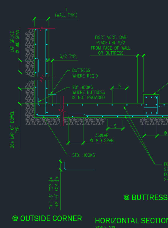
I wanted to share my own detail to show some solidarity, but I found out that I don't even have one. So here's my foundation wall corner detail. If I had to make a footing corner detail, it would be similar. (I almost regret posting this, because I found some mistakes, but whatever.)

Screenshot_2024-02-14_211432_dplv75.png


I have like thousands of details. I've spent hundreds of hours fixing them. There's no way I can go through all of them and make sure they're all 100%. I'll join the tough crowd; I honestly don't like your detail, but if it works, it works. Better than having no detail. I don't even like my own detail, so there's that.
 
Don't sweat the small details in details; the guys building them don't even have a set of your plans so they're going to do whatever they want anyway.
 
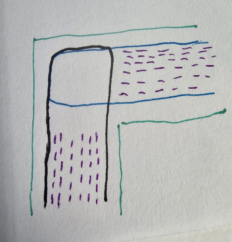
This question is as simple as how to transition the interior 6 bars(purple lines)through the corner. I will use the corner U bars.
20240215_124404_jvyynr.jpg
, instead of 90 degree bars.
 
Where I work it's the norm to use L bars for all the bars. I don't see a reason for u-bars.
 
U-bars have been shown by testing to develop more of the capacity of opening joints. About 90% effective, as opposed to 60% with standard hooks. But for closing joints, not much difference.
 
Status
Not open for further replies.

Part and Inventory Search

Sponsor

Back
Top