Continue to Site

Eng-Tips is the largest engineering community on the Internet

Intelligent Work Forums for Engineering Professionals

  • Congratulations IDS on being selected by the Eng-Tips community for having the most helpful posts in the forums last week. Way to Go!

Location of expansion tank and circulator relative to the plate heat exchanger

Status
Not open for further replies.

kikonas68

Mechanical
Feb 13, 2024
16
Hello.
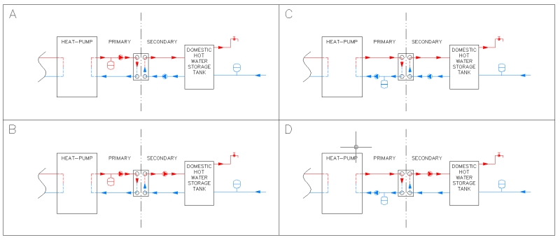
Which one of these arrangements is more correct than others regarding the location of circulators in both circuits?
HPE_vumgi3.png
 
Replies continue below

Recommended for you

Expansion tank has to be at point-of-no-pressure-change. that is as close as possible to the pump suction side.

All are right for the primary loop. None are correct for the water storage tank side.

On the domestics water side you are missing the return loop and check valve. If you don't have that, you wouldn't need an expansion tank.

Is this homework?
 
Let me rephrase slightly a little bit, by saying that the point of connection of the expansion tank is itself the point-of-no-pressure-change and therefore in general (except for solar circuits to my knowledge) the pump suction should be located as close as possible downstream of the expansion tank.

These are simplified sketches. I omitted many components(e.g. check valves, shut-off valves, deaerators, pressure relief valves, automatic filling unit for the primary etc.) in order to focus on the circulators (by the way there is actually a check valve before the expansion tank of the cold domestic water).

For the secondary I can understand case D) is wrong since we are pretty far away from the PONCP and also downstream of the PHE so a big pressure drop is expected resulting to low pressure at the suction of the pump (which is the thing we want to avoid).
By eliminating this case I cannot see any alternative to C) except if we bring the expansion tank into the loop before the circulator, which I haven't seen so far.
 
C looks pretty good to me.

Remember - More details = better answers
Also: If you get a response it's polite to respond to it.
 
Pump inlet is the point of no pressure change. Everything else will increase in pressure once the pump turns on. If the expansion tank is too far away (too much pressure drop between expansion tank and pump inlet) it will fluctuate with pump operation and will have less effective expansion volume and the membrane will wear out. You don't want that. The point of the expansion tank is to make up for expansion due to heat.

Since most pumps have a strainer on inlet, and an isolation valve, in rea life you will have a tiny bit of separation between pump and expansion tank. A and C aren't too bad since the domestic tank likely doesn't have much pressure drop assuming the piping distances are short. the HX will have significant pressure drop. I still would put the expansion tank as close to the pump as possible.

I don't know why solar loop makes a difference. Water expands due to heat regardless of where the heat came from.
 
HVAC-Novice said:
I don't know why solar loop makes a difference. Water expands due to heat regardless of where the heat came from.

I meant that in solar loop the expansion tank is located at the circulator discharge.
 
All of the drawings imply that you are circulating water through the domestic hot water tank from top to bottom. This would be like putting a stirrer in a hot water heater, which would considerably degrade its ability to provide high water temperature. The loop suction should draw from the bottom of the tank, where the coldest water is, and the loop return to the tank should be at a slightly higher level near the bottom. Thus, the already hot water at the top of the tank will not get immediately cooled by cold water addition. The cold water feed line should tie into the loop suction line so that it will get heated some before entering the tank. Heat pump efficiency is strongly affected by delta T across the heat exchangers.
 
Compositepro said:
All of the drawings imply that you are circulating water through the domestic hot water tank from top to bottom. This would be like putting a stirrer in a hot water heater, which would considerably degrade its ability to provide high water temperature.
i.e. I mess up the stratification. You're right! Thanks.
 
You want to bring the bottom (colder) water to the HX. You also should review where that tank actually has the pipe connections - it may not be like the schematic shows. Some tanks also have internal baffles etc. Ultimately you want the coldest water go to the HX since that will absorb the most heat. the warm water being pumped to the top of the tank also is fine because if you need to sue hot water, that already will be warm since the domestic hot water always will be there on top.


Solar or not, the expansion tank has to be on pump inlet side. What makes you think solar is different? A solar panel is a heat exchanger with Sun being on the other side. It could be electric heat or a gas flame providing the heat, it would be the same. the pump and expansion tank neither know nor care where the hat comes from.
 
HVAC-Novice said:
Pump inlet is the point of no pressure change. Everything else will increase in pressure once the pump turns on.
the expansion tank has to be on pump inlet side.
If the expansion tank is too far away (too much pressure drop between expansion tank and pump inlet) it will fluctuate with pump operation and will have less effective expansion volume and the membrane will wear out.

You are mistaking cause and effect here. OP has it right, the expansion tank is what makes the pressure constant at wherever the expansion tank is connected to the circuit. There is no reason why the pressure would remain constant at the pump suction without an expansion tank connected there. If you connect the expansion tank to the pump discharge, when the pump turns on the discharge pressure will stay constant and the suction pressure will drop.
 
HVAC-Novice said:
Expansion tank needs to be near pump INLET.
I don't disagree that in most cases it should be and usually is, I disagree with the assertion that it must. There is no physical reason why it must be on the pump inlet, only practical ones. I only bother to point it out because your previous statement about the expansion tank pressure fluctuating with pump operation and wearing out the membrane is so wildly inaccurate.
 
Expansion tank will experience increased pressure when pump starts and pressure will decrease when pump stops. That will wear the membrane. How significant that is depends on the size of the tank and number of start / Stops. But it is there.

I'm not aware of a single technical guide or book that recommends to put the expansion tank at the pump discharge side. Please provide a source if there is one.

You are right, one can install it wrong and it may appear to work. But it isn't good long term and will have more consequences. At minimum you decrease pressure in the system and that can lead to cavitation or de-aerators not working correctly. It all depends.

What is the damage of doing it the correct way and being sure it will work? Is doing it wrong and hoping MAYBE it works so much better?

 
HVAC-Novice said:
Expansion tank will experience increased pressure when pump starts and pressure will decrease when pump stops.
No, it won't. The expansion tank pressure only changes when the acceptance volume changes due to changes in system liquid volume. System liquid volume isn't impacted when the pumps turn off and on. Whether the pump is running or not therefore has no impact whatsoever on the expansion tank pressure. Only temperature change (causing volume change) in the system liquid impacts the expansion tank pressure.

Again, I am not advocating putting the expansion tank on the pump discharge I was using an example to attempt to explain to you how an expansion tank works. Expansion tanks aren't put at the pump suction to minimize bladder wear, they are usually put there because wherever you hook them up in the loop is the point that stays at constant pressure and the pump suction is usually where you want the pressure constant.
 
You are both essentially correct. If the expansion tank is on the outlet of the pump, there will be no problem unless the drop in suction pressure on the pump results in cavitation, which will the cause a change in volume, and movement of the diaphragm.
 
"the warm water being pumped to the top of the tank also is fine because if you need to sue hot water, that already will be warm since the domestic hot water always will be there on top."

That is not correct(except upon initial start-up of the tank when it contains only cold water). When the tank is full of hot water, and hot water is drawn out, cold water enters the system. One pass through the heat exchanger will not heat the water to full temperature. So if you return the loop to the top of the tank, you will be returning warmed water to hot water at the top, which will cool the hot water supply. You want to maximize stratification in the storage tank. As I said, It would be like adding a stirrer into a water heater, very counter productive.

Almost all electric water heaters now use dual heaters and thermostats, which is a very clever, patented invention. When hot water is consumed, cold water enters at the bottom, the bottom heater/thermostat turns on and starts warming this water without any cooling of the hot water at the top of the tank. As the thermocline in the tank between the hot and warm water rises in the tank, the upper heater/thermostat at the middle of the tank turns on and the lower heater turns-off. Thus the water already warmed by the lower heater gets further warmed to a useable temperature. This significantly extends the amount of time before running out of hot water for you shower. After you stop consuming hot water the upper heater only has to heat the top half of the tank to before more usefully hot water is again available (recovery time is cut in half). When the top half of the tank is hot the upper heater turns off and the lower heater turns on until the full tank is hot. If only small amounts of water are used at a time, the upper heater will never turn on, and only the lower heater operates.

Keep in mind that the water in the tank is generally very still but the hot water around the heating elements rises quite rapidly as it mixes with surrounding cooler water. The heating elements home water heaters are generally 4500 Watts 240 volts. They will operate perfectly on 120 volts, in which case they give only 1500 Watts. The hot water capacity per day will be reduced but not the storage capacity for short term supply.
 
Regarding solar known manufacturers like Reflex, Caleffi etc. say in solar should be inversely. I/m still trying to find out why [bigsmile] though. Maybe something else than pump cavitation prevails (e.g. minimise pressure into the collectors which on the other hand favors evaporation combined to high temperatures-beyond 100°C).
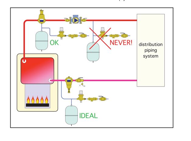
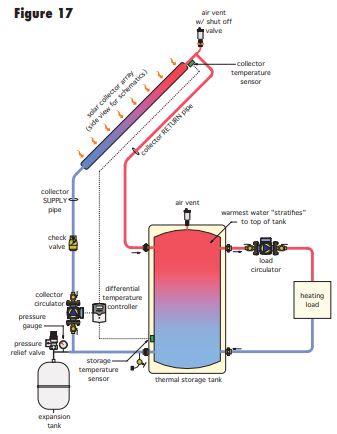
 
Can yo cite the source? There may be more context needed.
Right here Caleffi show the Expansion tank upstream of the pump right on the cover page

Here they show it wrong in some locations. They sell this solar station with it being wrong. My best guess is the pressure in a solar system is so high that the negative pressure at the pump inlet doesn't matter. and that is a variable speed pump.

the only real difference in a solar system is that temperatures can be quite higher than in an HVAC system and the system is under much higher pressure. Pressure will be especially high if the tank is in a basement and the panels typically on a roof. That's why they get away with doing it wrong. Hope no one has a situation where the tank and that solar station is above the panels.

Caleffi also say this

Capture_lm4jig.jpg

And their picture above with the boiler also is not 100% OK. They show the location at boiler inlet as ideal and the one at pump inlet just as "OK". I assume this is to protect the expansion tank from heat. What they should do is have both the pump and the expansion tank at boiler return. The pump also doesn't like heat. Basically "Expansion Tank - Pump - Boiler inlet"

It wouldn't be the first time manufacturer does something wrong. Aerco boiler manuals had the primary pump on the wrong location for a long time. if you really want to do what their product seems to suggest, you should contact Caleffi and specifically ask.
 
Compositepro said:
the drop in suction pressure on the pump results in cavitation, which will the cause a change in volume, and movement of the diaphragm.
I doubt that cavitation in a pump inlet would noticeably change the system volume. In any case, that's clearly not what HVAC-Novice is talking about:
HVAC-Novice said:
If the expansion tank is too far away (too much pressure drop between expansion tank and pump inlet) it will fluctuate with pump operation and will have less effective expansion volume and the membrane will wear out.
This statement is simply incorrect. The expansion tank pressure does not fluctuate with pump operation, only system volume/temperature. Moving on.

In solar applications it looks like the expansion tank is located on the pump discharge so under no demand conditions when the fluid in the collectors boils the expansion tank is in direct communication with the collector and not behind the pump discharge check.
"Because all pressurized systems have the potential to “steam-back”, it is considered a best practice to install the check valve on the return piping (going back to the collector) and to locate the expansion tank above the check valve. When a system goes into “steam-back”, steam forms inside the collector and pushes any remaining fluid down through the return line and ending up in the expansion tank. Therefore the expansion tank must not be isolated from the collector on the return line (flow to the collector)."
 
The check valve isn't relevant here since the expansion tank is connected to the collector through the return side of the loop (from collector through tank).

and the expansion tank isn't sized for boiling water. It is sized to accommodate expanding liquid, not steam. Steam has 1600 times the volume of water. I don't want to imagine the size the expansion tank one would need....

Unless there is a stated reason why it is better, I wouldn't trust Caleffi on this one. Here this from Caleffi as well:
Caleffi_ean5pm.jpg


Maybe Caleffi just determined at the high pressures in solar system it won't matter. but the pump inlet still is the better (safer) choice unless there is a good reason(which we still don't know)

I recommend to have a look at the book by John Siegenthaler I linked above. He also has some more recent solar specific books (I don't have that, but imagine it to be good).
 
Status
Not open for further replies.

Part and Inventory Search

Sponsor