Continue to Site

Eng-Tips is the largest engineering community on the Internet

Intelligent Work Forums for Engineering Professionals

  • Congratulations waross on being selected by the Eng-Tips community for having the most helpful posts in the forums last week. Way to Go!

Line size calculation 3

Status
Not open for further replies.

Asisraja D

Mechanical
Jan 3, 2024
160
Hello professionals
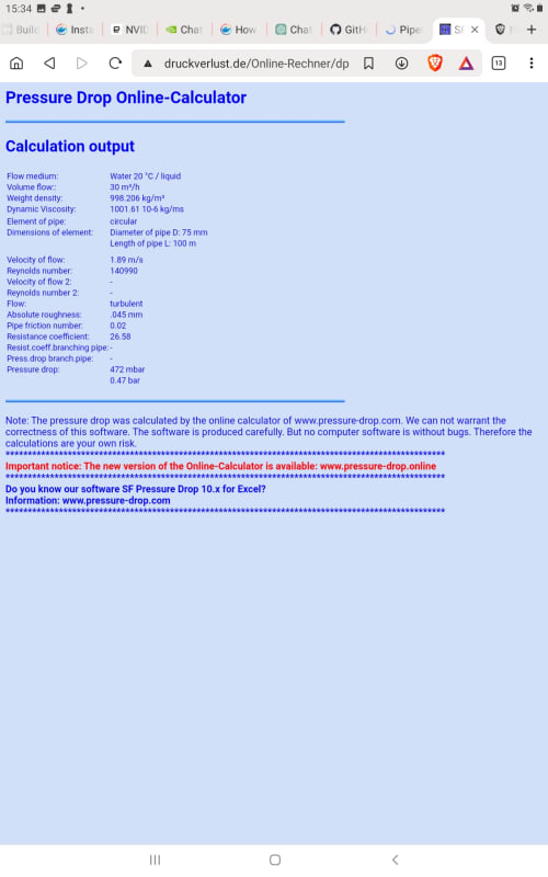
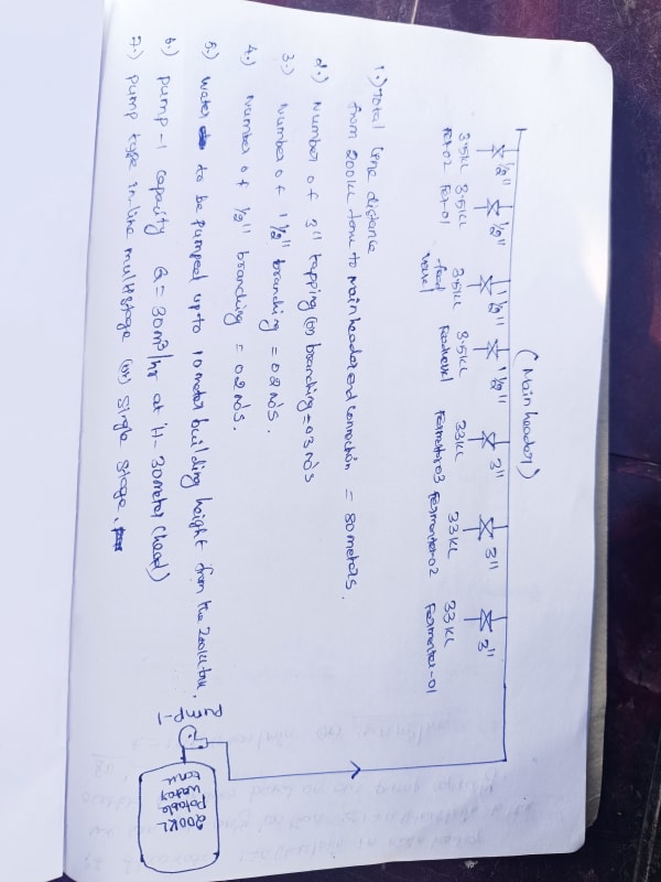
Thank you for your comments. We plan to route potable water to our block where we installed 33kl fermenters and we select pump capacity for 30 m3/hr with 30mtr pump head. The problem is I don't know how much header size would be efficient to fill up the fermenters fast. I have attached my hand sketch for clarity. All of your time is precious so when you have time consider my post again thank you all.
 
 https://files.engineering.com/getfile.aspx?folder=1e47febe-b9ce-412a-9c72-3525006e3a56&file=IMG_20240221_164841.jpg
Replies continue below

Recommended for you

Shvet tha line MOC is SS304 (ASTM A312).
Pump capacity is calculated by our managing director but he didn't tell us the header size.
 
Good liquid fluid velocities are between 1 and 3 m/s.
So always start with trying to selecting a pipe diameter that gives a fluid velocity of 2m/s

30m3/hr = 0.0083 m3/sec
Pipe area of a 2" diameter pipe = 0.002 m2
Velocity = 0.0083/0.002 = 4.15 m/s

That's a bit fast, so try a 75mm diameter

Assume a 75mm diameter and
Pipe area = 0.0045m2
Velocity = 0.0083/ 0.0045 = 1.8 m/s.
That is greater than 1 and less than 3m/s, so
Check your pressure drop of that 75mm pipe with an 8 liters/s flow.

Screenshot_20240221-153426_Brave_ulylep.jpg


0.47 bar per 100m length.


IMG_20240221_164841_gg2nqe.jpg


You have 80m so 0.47barg x 80/100 = about 0.4 bars of friction loss
= about 0.47 x 10 = about 5m head and
10m lost to elevation

15m total head loss.

Head remaining at end of line is 30 m pump - 15m friction and elevation leaves 15m at EOL.
Probably OK, since the flow will not be 8l/s through the whole 80m length.
15m head is about 1.5 barg.
Is that enough pressure at the last fitting?


--Einstein gave the same test to students every year. When asked why he would do something like that, "Because the answers had changed."
 
1503-44 1.5barg pressure is enough for our filling requirements because we need just filling process we are not using any heat transfer like that.
thank you so much sir for making your valuable time for helping me. I will try 75mm dia pipe based on our pipe fittings and line lengths. This is really very good sign of seeing likely minded people to help each other through this forums. Again thank you so much sir for your valuable response ☺️.
 
You are Welcome.

I just edited the above to include the Web site pressure drop calculation results. Please review.

--Einstein gave the same test to students every year. When asked why he would do something like that, "Because the answers had changed."
 
Note that I used roughness factor for steel pipe. Plastic pipe is much smaller at about 0.01mm.

--Einstein gave the same test to students every year. When asked why he would do something like that, "Because the answers had changed."
 
1503-44 and shvet I heartfully thank you for both of you for sharing your knowledge and helping me in this. It is very pleasure for me to communicating with you all. Again thank you so much professionals.
 
Sounds like that could be OK. Recalculate the end of line pressure. 1 barg of remaining pressure may not be enough in some circumstances.

Another important point is to keep velocities under control. Any velocity through the smaller attaching pipes of 4 to 5 m/s could easily create the pipe banging water hammer noises. Everybody gets upset when those happen, day or night.

--Einstein gave the same test to students every year. When asked why he would do something like that, "Because the answers had changed."
 
1503-44 ok sir I will calculate the EOL pressure based on your valuable guidance. This is really a lot of learning in this single thread with your valuable communication sir. I again thank you so much sir 😊🙏 I will be grateful for you forever. I will be contacting you with this forums all my life. You are really great sir. Again thank you so much sir.
 
Careful, not too much praise! We don't want to entice BigInch out of retirement. [2thumbsup]

Good Luck,
Latexman

 
🤫 Do Not Disturb 🤫 🏝 🏴󠁧󠁢󠁳󠁣󠁴󠁿 🇮🇨 🤫 No Moleste 🤫

--Einstein gave the same test to students every year. When asked why he would do something like that, "Because the answers had changed."
 

Branan Rules of Thumb for Chemical Engineers 3rd Ed [URL unfurl="true" said:
https://a.co/d/9FbOB6V[/URL]]Recommended Velocity
Engineers determine pipe sizes by analyzing performance and economic parameters. Over the years, an enormous number of systems have been designed, installed, and operated. Those systems often share similar
characteristics since they were built from the same catalog of available equipment, such as pumps and control valves. It’s reasonable, then, to begin a new design project using existing system designs as a starting point.
Therefore, a Rule of Thumb is to use tables of suggested velocity for an initial determination of pipe size.
The values in the tables have been widely disseminated,and have long since lost their original source. Also, the suggested velocities are often given as ranges. You are cautioned to use the information judiciously and perform your own analysis as your piping system design develops.
Factors to consider regarding velocity:
• Low velocity may indicate a larger pipe diameter than is necessary which raises cost.
• Low calculated velocity may result in the pipe running partially full in horizontal runs.
• Low velocity can lead to laminar flow conditions which may promote fouling and will definitely hinder heat transfer (if applicable).
• High velocity may be noisy.
• High velocity can cause damage to the pipe due to erosion.
• Certain components such as check valves and control valves are designed to operate with a specific flow range; manufacturers of the components recommend minimum lengths of pipe of specified diameter upstream and downstream of their device.
Some more comments by type of service:
Clean single-phase fluids (gas or liquid) tolerate the widest range of velocity. Generally use 1.5 to 4.0 m/s (5 to 12 ft/s) for liquids, or 15 to 40 m/s (50 to 120 ft/s) for gases as a starting point. Use a Net Present Value (NPV) economic analysis to balance the initial capital cost for the piping with energy cost for moving the fluid.
...
Pipe material must be factored into the analysis. Softer materials, such as thermoplastics and copper, are more susceptible to erosion than hard materials, such as austenitic stainless steels.
...

Table 1-1 Suggested starting point for pipe sizing using fluid velocity or pressure drop criteria
...
Water, average service 1.5 to 3 m/s
...
Water, pump suction 0.3 to 1.5 m/s
...
Water, wastewater, pump suction 1 to 1.8 m/s
Water, wastewater, pump discharge 1 to 2.5 m/s
Water, wastewater, gravity 0.6 to 2.5 m/s

Quickly Estimating Pipe Lengths
Here’s a simple way to get started on a project. The objective is to create a list of pipe segments, with size and length for each, which can be used for preliminary calculations and cost estimation.
1. From a Process Flow Diagram and conceptual or preliminary General Arrangements, make a sketch that mimics the PFD in both Elevation and Plan.
2. Write down measurements in x-y-z coordinates.
3. Use those measurements to estimate the physical length of each pipe segment.
4. Add a factor of 25% to account for errors in this highly conceptual procedure.
5. Add an additional factor of 50% to 100% to account for fittings. Alternatively, if fittings are considered to be fairly well known (elbows, tees, valves, instruments, and orifices) then refer to the Equivalent Length section in this chapter to obtain data.
Example: Refer to the sketch in Figure 1-0.
Line 215 length = 2 m + 2.5 m = 4.5 m (ignore liquid level in R-200)
Line 216 length = 6 m + 2.5 m + 6 m + 10 m + 1.5 m = 26 m
1.png

image.png
 
So what is normal maximum operating pressure in the fermenters / feed vessels ? Any control valves / throttle valves at the inlet to each of these ? It couldnt be just an uncontrolled open line into these vessels ?
 
Guys. Start a new thread.

--Einstein gave the same test to students every year. When asked why he would do something like that, "Because the answers had changed."
 
Or not.

--Einstein gave the same test to students every year. When asked why he would do something like that, "Because the answers had changed."
 
georgeverghese you are correct. There is one control valve right now I don't know about the details of them but the fermenter jacket inlet size is 1 1/2" (3 inlets on the jacket same as 3 outlets) as you know the fermenter is 33kl. We have connected the 3 inlets nozzle with common manifold of 3" size. I am handling the utility side piping like main headers and sub headers to the fermenter and rest of the internal piping upto vessel is providing by contractors. I will give you normal operating pressure and control valve details after I collect from the contractors. Thank you sir
 
shvet sir The concept you guide me here is really very new to me and it is bit hard to catch up for my knowledge because I am an project engineer with 3 years of experience in this field but the knowledge you have shared here is really very much appreciated and it is going to be helpful for me when I understand the concept of yours. I will take my time to read and search about the design considerations of equivalent length of pipes and so. Thank you so much sir for your guidance ☺️.
 
Status
Not open for further replies.

Part and Inventory Search

Sponsor