Hello all, I've got another Revit modeling question as regards a structural footing. A note in the drawing (from 1968) specifies that:
"The maximum wall footing ste-off shall be 2'-0" vertical spaced not less than 4'-0" o.c. Footing step-offs are indicated on plans by the symbol S-strikethrough"
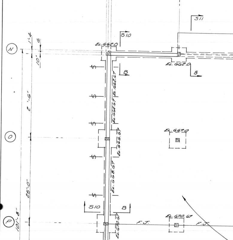
The drawing shows this:

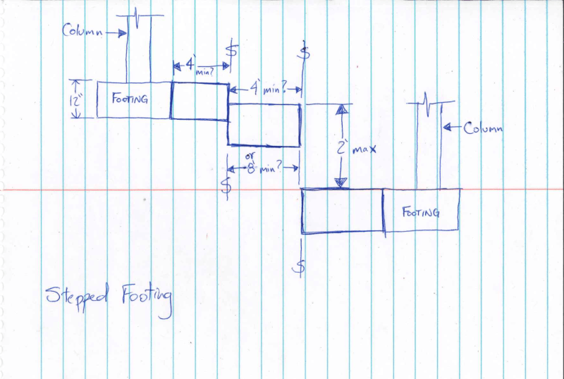
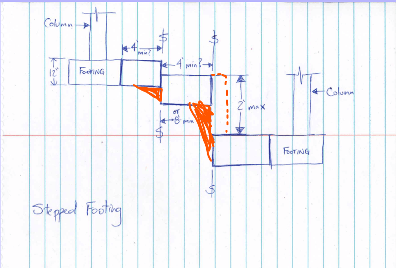
Does the s-strikethrough represent the beginning or the middle of the footing step-off? My assumption is that it's the beginning. I have a sketch of a section of footing step-off's:

I'm also a bit confused as to what "4'-0" o.c." off-center with regards to what exactly? Thanks in advance for the help!
"The maximum wall footing ste-off shall be 2'-0" vertical spaced not less than 4'-0" o.c. Footing step-offs are indicated on plans by the symbol S-strikethrough"
The drawing shows this:

Does the s-strikethrough represent the beginning or the middle of the footing step-off? My assumption is that it's the beginning. I have a sketch of a section of footing step-off's:

I'm also a bit confused as to what "4'-0" o.c." off-center with regards to what exactly? Thanks in advance for the help!

