Continue to Site

Eng-Tips is the largest engineering community on the Internet

Intelligent Work Forums for Engineering Professionals

  • Congratulations KootK on being selected by the Eng-Tips community for having the most helpful posts in the forums last week. Way to Go!

Direct Stiffness Method - Why am I getting incorrect signs

Status
Not open for further replies.

Tygra_1983

Student
Oct 8, 2021
121
Hi there,

I was wondering if someone might know why I am getting incorrect signs for my structure that I am working on using the Direct Stiffness Method? I am following the procedure that I was taught when I was at University and I can't completely remember everything. I am designing a seven-storey structure that looks like this:
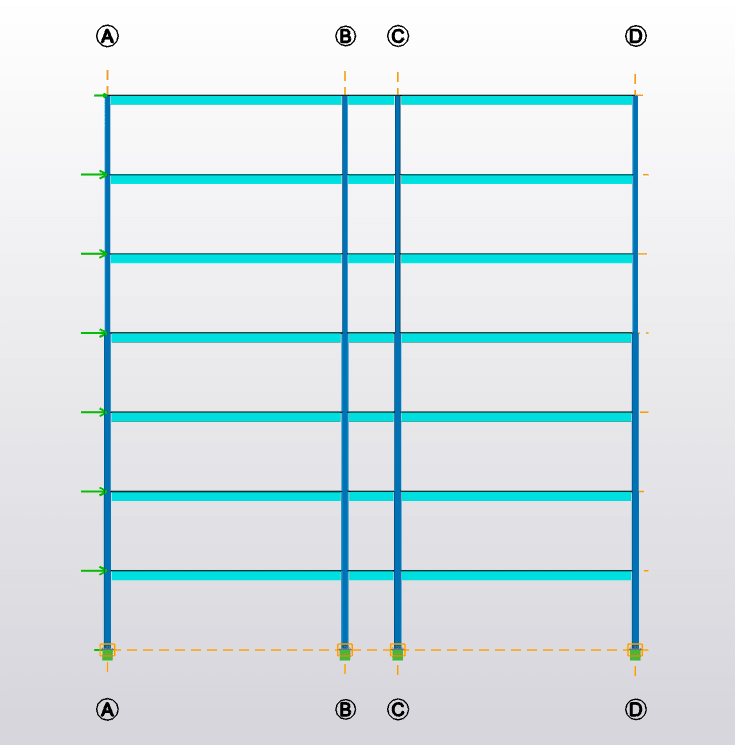
7_storey_structure_iopbno.png


The magnitude of the forces I am getting is accurate, but the signs are incorrect.

Here are the bending moment on the structure:
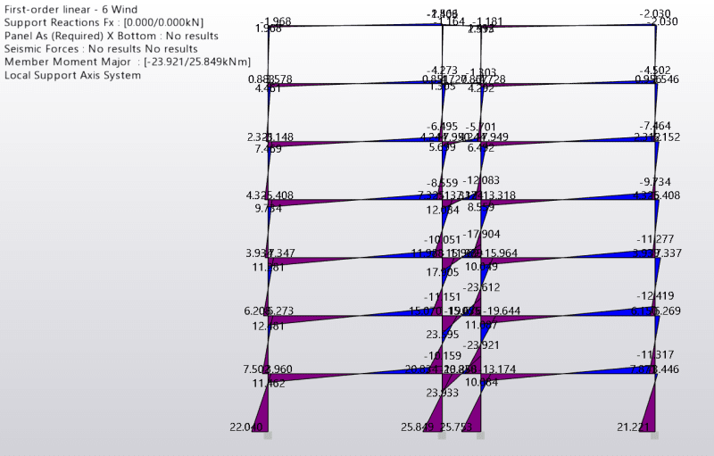
bm_frame_ldubp1.png


You might not be able to see, but for the columns, you get a positive bending moment at the bottom of each storey and a negative bending moment at the top of the storey - this pattern is the same for each storey.

In my code I am getting positive bending moments at the top and the bottom, but like I said the magnitude is quite accurate.

Rather than post the entirity of my code, lets focus on a single column.

The local stiffness matrix for a column has the form:
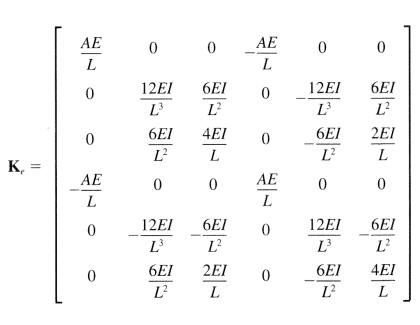
LSM_firpff.png


And I set up the transformation matrix as follows:


Code:
Code:
T =

  6x6 table

              U1    V1    theta1    U2    V2    theta2
              __    __    ______    __    __    ______

    U1         0    1       0        0    0       0  
    V1        -1    0       0        0    0       0  
    theta1     0    0       1        0    0       0  
    U2         0    0       0        0    1       0  
    V2         0    0       0       -1    0       0  
    theta2     0    0       0        0    0       1


To compute the global stiffness matrix you use the equation:

Kglobal = T(transpose)*KLocal*T


This will give you the global stiffness matrix! You can then proceed to find the displacements and rotations. Then you can find the internal forces on the structure.

I guess the thing to look at is the transformation matrix. Does it seem correct to you? The local stiffness matrix is definitely correct.

Many thanks in advance
 
Replies continue below

Recommended for you

loads vs reactions ? is one method determining the load/reaction at a point and the other the reaction/load ?

"Hoffen wir mal, dass alles gut geht !"
General Paulus, Nov 1942, outside Stalingrad after the launch of Operation Uranus.
 
I would manually go through the full force recovery at one of the joints

Get the nodal displacement vector and compare with the commercial software package, assuming the node displacement vector is the same then you can narrow it down into something wrong with your local force recovery stage.

Also remember that order of matrix multiplication matters, so Kg = T[sup]t[/sup]K[sub]L[/sub]T should be multiplied equivalent to (T[sup]t[/sup]*K[sub]L[/sub]) * T.
 
I have gone through the recovery at the joints and in the software and I have found the rotations are positive. However, in my MATLAB code the rotations are negative. The magnitude is the same though. I'm not sure how to ammed my code to fix this. I asked in my fist post whether the transformation matrix is correct? Could this be given me the incorect signage?
 
Your local stiffness matrix and transformation matrix appear to be accurate assuming you defined the columns from bottom node to top node.
 
see, that may be another thing causing this sign issue ... the co-ordinate axes assumed ... You've numbered bottom up, that may define the co-ord axes for the beams, that may be different to your global co-ords.

You need to figure out are the +ve moments a load or a reaction.

I'm confused by the FEM output. At the top LH corner things appear to balance ... +1.968 and -1.968 balance, and red and blue also balance. But 1/2 way we have (red) 4.326 from the column and 5.408 from the horizontal and (blue) +9.734 ... doesn't balance ??

"Hoffen wir mal, dass alles gut geht !"
General Paulus, Nov 1942, outside Stalingrad after the launch of Operation Uranus.
 
rather than looking at a big multi-story frame, try modeling just a single frame that will make it easier to troubleshoot your code.
You could go even simpler and just model a fixed-fixed vertical column and enforce a rotation at the top.
 
rb1957 said:
I'm confused by the FEM output. At the top LH corner things appear to balance ... +1.968 and -1.968 balance, and red and blue also balance. But 1/2 way we have (red) 4.326 from the column and 5.408 from the horizontal and (blue) +9.734 ... doesn't balance ??

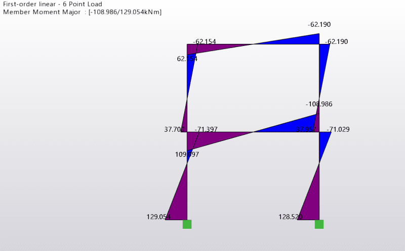
Yes, I just checked, and that is very strange. The signs appear incorrect. You need -4.325 to balance, but its positive giving an unblanced moment of 8.651 kNm. The software is Tekla Structural Designer (student version).
 
Celt83 said:
rather than looking at a big multi-story frame, try modeling just a single frame that will make it easier to troubleshoot your code.

I have already done that, because I have also asked on another forum, and one of the guys suggested the same thing. So I did it and still got the same issue - accurate magnitudes, but incorrect signs. As the code is much less I will post it. This time a two storey one bay frame.

Code:
clear, clc, close all

% Structural Propeties
Ic = 22760/100^4;
E = 2.1E+08;
Ac = 170.2/100^2;
h = 4;
L = 6;

% Local stiffness matrix for columns
Kc = [E*Ac/h 0 0 -E*Ac/h 0 0;
      0 12*E*Ic/h^3 6*E*Ic/h^2 0 -12*E*Ic/h^3 6*E*Ic/h^2;
      0 6*E*Ic/h^2 4*E*Ic/h 0 -6*E*Ic/h^2 2*E*Ic/h;
      -E*Ac/h 0 0 E*Ac/h 0 0;
      0 -12*E*Ic/h^3 -6*E*Ic/h^2 0 12*E*Ic/h^3 -6*E*Ic/h^2;
      0 6*E*Ic/h^2 2*E*Ic/h 0 -6*E*Ic/h^2 4*E*Ic/h]

% Local stiffness matrix for beams
Kb = [E*Ac/L 0 0 -E*Ac/L 0 0;
      0 12*E*Ic/L^3 6*E*Ic/L^2 0 -12*E*Ic/L^3 6*E*Ic/L^2;
      0 6*E*Ic/L^2 4*E*Ic/L 0 -6*E*Ic/L^2 2*E*Ic/L;
      -E*Ac/L 0 0 E*Ac/L 0 0;
      0 -12*E*Ic/L^3 -6*E*Ic/L^2 0 12*E*Ic/L^3 -6*E*Ic/L^2;
      0 6*E*Ic/L^2 2*E*Ic/L 0 -6*E*Ic/L^2 4*E*Ic/L]

% number of nodes
n = 18


% Transformation matrix for Member 1
T1 = zeros(6,n)
T1(2,1) = -1;
T1(1,2) = 1;
T1(3,3) = 1;
T1(5,4) = -1;
T1(4,5) = 1;
T1(6,6) = 1;

% Transformation matrix for Member 2
T2 = zeros(6,n)
T2(2,4) = -1;
T2(1,5) = 1;
T2(3,6) = 1;
T2(5,7) = -1;
T2(4,8) = 1;
T2(6,9) = 1;

% Transformation matrix for Member 3
T3 = zeros(6,n)
T3(2,10) = -1;
T3(1,11) = 1;
T3(3,12) = 1;
T3(5,13) = -1;
T3(4,14) = 1;
T3(6,15) = 1;

% Transformation matrix for Member 4
T4 = zeros(6,n)
T4(2,13) = -1;
T4(1,14) = 1;
T4(3,15) = 1;
T4(5,16) = -1;
T4(4,17) = 1;
T4(6,18) = 1;

% Transformation matrix for Member 5
T5 = zeros(6,n)
T5(1,4) = 1;
T5(2,5) = 1;
T5(3,6) = 1;
T5(4,13) = 1;
T5(5,14) = 1;
T5(6,15) = 1;

% Transformation matrix for Member 6
T6 = zeros(6,n)
T6(1,7) = 1;
T6(2,8) = 1;
T6(3,9) = 1;
T6(4,16) = 1;
T6(5,17) = 1;
T6(6,18) = 1;

% Combine transformation matrices into one vector
T = cat(3,T1,T2,T3,T4,T5,T6);

% Assemble global matrix
for i = 1:6
    Km(:,:,i) = (T(:,:,i)'*Kc)*T(:,:,i)
    if i > 4
        Km(:,:,i) = (T(:,:,i)'*Kb)*T(:,:,i)
    end
end

% sum up global matrices
Kt = Km(:,:,1)
for i = 1:5
    Kt = Kt + Km(:,:,i+1);
end

% Apply boundary conditions
Kt(:,[1,2,3,10,11,12]) = [];
Kt([1,2,3,10,11,12],:) = [];

% Assign 50 kN to each storey at their respective nodes
F = zeros(n,1);
F([4,7]) = 50;

% Apply the boundary conditions for the force vector
F([1,2,3,10,11,12]) = [];

% Solve for displacewments
U = inv(Kt)*F

% Re-construct a column vector containing all displacements
Ux = [0;0;0;U(1:6);0;0;0;U(7:12)]

% Compute internal forces for ecah member
for i = 1:6
    Fx(:,i) = T(:,:,i)*Ux
    Vx(:,i) = Kc*Fx(:,i)
    if i > 4
       Vx(:,i) = Kb*Fx(:,i) 
    end
end

% set up table to display internal forces
rows = {'Axial 1','Shear 1','Moment 1','Axial 2','Shear 2','Moment 2'}
T = array2table(Vx,...
    'VariableNames',{'Member 1','Member 2','Member 3','Member 4','Member 5','Member 6'},'RowNames',rows)

T =

  6x6 table

                Member 1    Member 2    Member 3    Member 4    Member 5    Member 6
                ________    ________    ________    ________    ________    ________

    Axial 1     -57.396     -20.657      57.396      20.657      24.838       25.04 
    Shear 1      50.121       24.96      49.879       25.04      -36.74     -20.657 
    Moment 1      128.1       37.89      127.52       38.17     -110.28     -61.949 
    Axial 2      57.396      20.657     -57.396     -20.657     -24.838      -25.04 
    Shear 2     -50.121      -24.96     -49.879      -25.04       36.74      20.657 
    Moment 2     72.388      61.949      71.991      61.991     -110.16     -61.991

Here, is the model in Tekla:

2_storey_structure_fjt8vo.png


Compare the table in the code to Tekla and you can see differencves in sign.
 
your results are accurate, the member local end results are the results applied to the end of the member. The internal member moment may have the opposite sign.
 
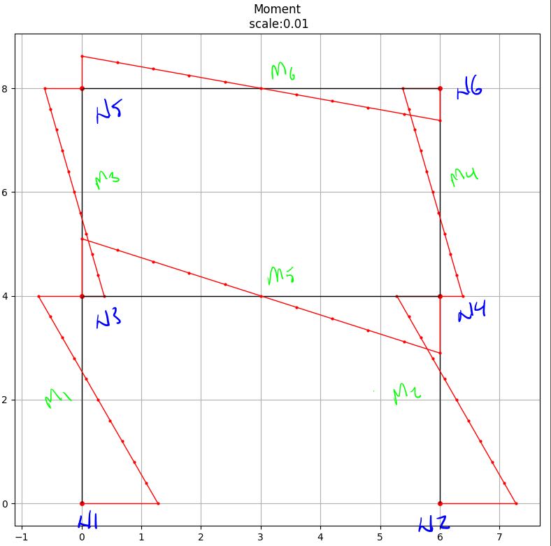
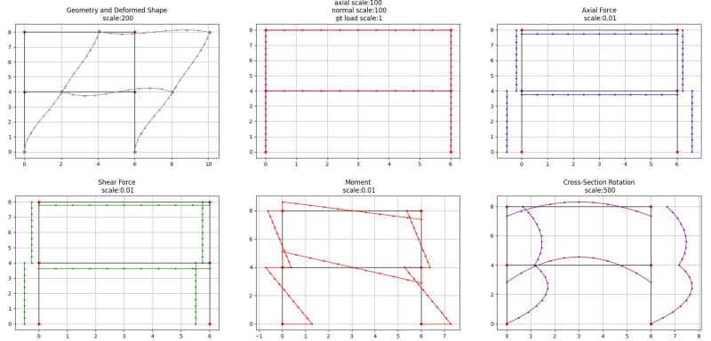
It appears Tekla may also be using a different sign convention. Here are the results I get:
Capture_uxbyd4.jpg


Capture_xbu7ag.jpg


[pre]
Displacements:
-----------------------------------------------
Node | Ux | Uy | Rz |
-----------------------------------------------
N1 | 0.0000E+00 | 0.0000E+00 | 0.0000E+00 |
-----------------------------------------------
N2 | 0.0000E+00 | 0.0000E+00 | 0.0000E+00 |
-----------------------------------------------
N3 | 1.0255E-02 | 6.4234E-05 |-2.3311E-03 |
-----------------------------------------------
N4 | 1.0213E-02 |-6.4234E-05 |-2.3238E-03 |
-----------------------------------------------
N5 | 2.0351E-02 | 8.7352E-05 |-1.3243E-03 |
-----------------------------------------------
N6 | 2.0309E-02 |-8.7352E-05 |-1.3270E-03 |
-----------------------------------------------


-----------------------------------------------
Reactions:
-----------------------------------------------
Node | Fx | Fy | Mz |
-----------------------------------------------
N1 |-5.0121E+01 |-5.7396E+01 | 1.2810E+02 |
-----------------------------------------------
N2 |-4.9879E+01 | 5.7396E+01 | 1.2752E+02 |
-----------------------------------------------
N3 |-1.0658E-14 |-7.1054E-15 | 1.4211E-14 |
-----------------------------------------------
N4 | 7.6739E-13 |-7.1054E-15 | 8.5265E-14 |
-----------------------------------------------
N5 |-1.7373E-12 |-7.1054E-15 | 0.0000E+00 |
-----------------------------------------------
N6 | 6.0396E-13 |-1.4211E-14 | 0.0000E+00 |
-----------------------------------------------


------------------------------------------------------
Member Local End Forces:
------------------------------------------------------
Member |joint | Ax | Vy | Mz |
------------------------------------------------------
M1 | i |-5.7396E+01 | 5.0121E+01 | 1.2810E+02 |
| j | 5.7396E+01 |-5.0121E+01 | 7.2388E+01 |
------------------------------------------------------
M2 | i | 5.7396E+01 | 4.9879E+01 | 1.2752E+02 |
| j |-5.7396E+01 |-4.9879E+01 | 7.1991E+01 |
------------------------------------------------------
M3 | i |-2.0657E+01 | 2.4960E+01 | 3.7890E+01 |
| j | 2.0657E+01 |-2.4960E+01 | 6.1949E+01 |
------------------------------------------------------
M4 | i | 2.0657E+01 | 2.5040E+01 | 3.8170E+01 |
| j |-2.0657E+01 |-2.5040E+01 | 6.1991E+01 |
------------------------------------------------------
M5 | i | 2.4838E+01 |-3.6740E+01 |-1.1028E+02 |
| j |-2.4838E+01 | 3.6740E+01 |-1.1016E+02 |
------------------------------------------------------
M6 | i | 2.5040E+01 |-2.0657E+01 |-6.1949E+01 |
| j |-2.5040E+01 | 2.0657E+01 |-6.1991E+01 |
------------------------------------------------------


------------------------------------------------------
Member Global End Forces:
------------------------------------------------------
Member |joint | Fx | Fy | Mz |
------------------------------------------------------
M1 | i |-5.0121E+01 |-5.7396E+01 | 1.2810E+02 |
| j | 5.0121E+01 | 5.7396E+01 | 7.2388E+01 |
------------------------------------------------------
M2 | i |-4.9879E+01 | 5.7396E+01 | 1.2752E+02 |
| j | 4.9879E+01 |-5.7396E+01 | 7.1991E+01 |
------------------------------------------------------
M3 | i |-2.4960E+01 |-2.0657E+01 | 3.7890E+01 |
| j | 2.4960E+01 | 2.0657E+01 | 6.1949E+01 |
------------------------------------------------------
M4 | i |-2.5040E+01 | 2.0657E+01 | 3.8170E+01 |
| j | 2.5040E+01 |-2.0657E+01 | 6.1991E+01 |
------------------------------------------------------
M5 | i | 2.4838E+01 |-3.6740E+01 |-1.1028E+02 |
| j |-2.4838E+01 | 3.6740E+01 |-1.1016E+02 |
------------------------------------------------------
M6 | i | 2.5040E+01 |-2.0657E+01 |-6.1949E+01 |
| j |-2.5040E+01 | 2.0657E+01 |-6.1991E+01 |
------------------------------------------------------[/pre]
 
Thanks for taking the time to go through the problem, Celt83!

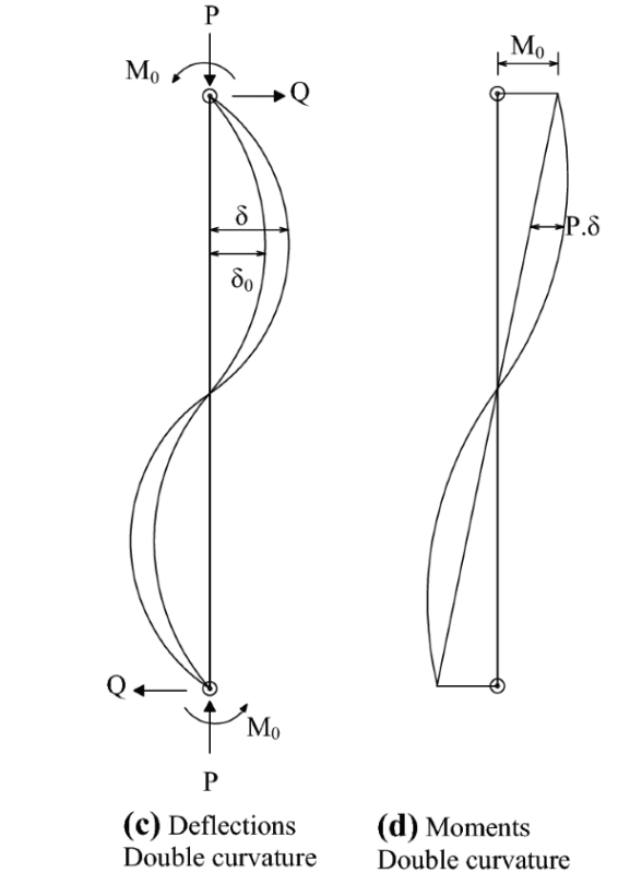
However, you are getting the same results as me. Considering member 1, both your moments are positive (like mine). How is this? A 2D structure under a lateral load causes the columns and beams to bend in double curvature and produce the corrosponding BM diagram.

d_curvature_btl2fk.png


Thus, the sign of the moment at the bottom changes when it passes the point of contraflexure. I am puzzled why we are not getting this.
 
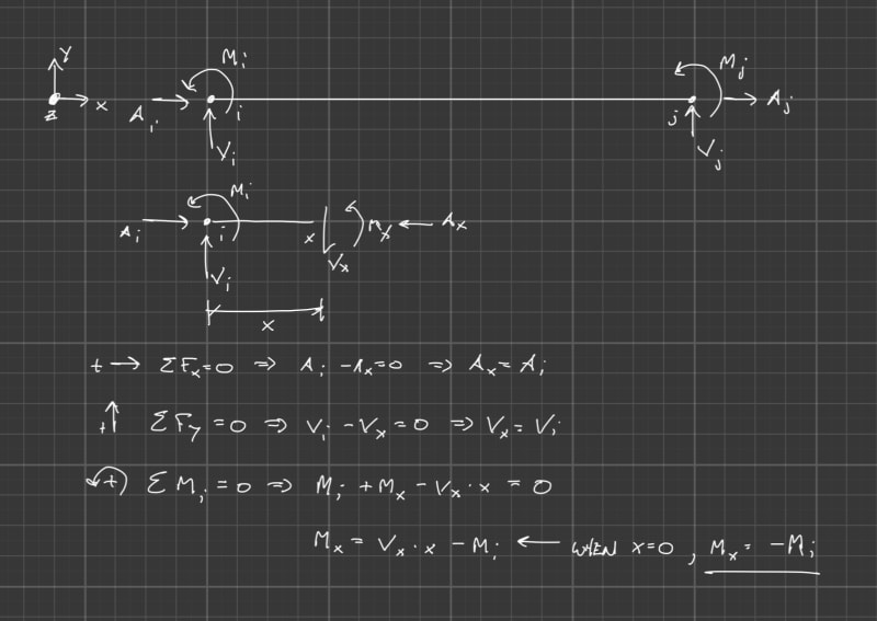
Refer to your left diagram the applied end moments are Mo and both are in the same direction (the same sign). The direct stiffness results are the applied moments to the end of the member the internal moment, the plotted moment diagram from tekla, comes from the application of statics/mechanics along the length of the member.
 
I wouldn't necessarily call it a problem, it is more just understanding that the direct stiffness method is all about the joints and the data that you get out of it is the joint displacements and joint forces. You need to then post-process the joint data to get at the internal member data, the commercial software does the post-process black box so all you get out of it usually are the internal member values (understanding the software packages sign conventions is also critical).
 
You were focused on just the moments, but if you look at your local member shears and axial forces you'll see they swap sign however the internal member response will be a constant shear and axial force.
 
Celt83 said:
I wouldn't necessarily call it a problem, it is more just understanding that the direct stiffness method is all about the joints and the data that you get out of it is the joint displacements and joint forces.

Yes, agreed. Due to my inexperience I assumed that the stiffness method would give me the actual internal member data. I had no clue that I would have to do another step to get the internal member response. Thanks for your help, Celt83.

Celt83 said:
You were focused on just the moments, but if you look at your local member shears and axial forces you'll see they swap sign however the internal member response will be a constant shear and axial force.

Yes, I noticed that. It was another thing that was frustrating me because I thought the stiffness method would give a constant shear and axial force.
 
"It was another thing that was frustrating me because I thought the stiffness method would give a constant shear and axial force." ... can you explain what you mean by this, as your simple elements have constant shear and axial load ?
(at least that's how I read the pictures)

"Hoffen wir mal, dass alles gut geht !"
General Paulus, Nov 1942, outside Stalingrad after the launch of Operation Uranus.
 
rb1957 said:
can you explain what you mean by this, as your simple elements have constant shear and axial load ?
(at least that's how I read the pictures)

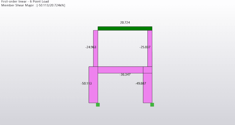
Basically, what I have learnt from Celt83 the stiffnesss method does not solve the statics/mechanics along the length of the member. If you look in my table and Celt83's you will see that for the axial and shear force we get positive and negative values at each joint for a given member. Whereas, in Tekla it will give contant shear:

shear_lvjz5k.png


Compare with my results

Code:
                Member 1    Member 2    Member 3    Member 4    Member 5    Member 6
                ________    ________    ________    ________    ________    ________

    Axial 1     -57.396     -20.657      57.396      20.657      24.838       25.04 
    Shear 1      50.121       24.96      49.879       25.04      -36.74     -20.657 
    Moment 1      128.1       37.89      127.52       38.17     -110.28     -61.949 
    Axial 2      57.396      20.657     -57.396     -20.657     -24.838      -25.04 
    Shear 2     -50.121      -24.96     -49.879      -25.04       36.74      20.657 
    Moment 2     72.388      61.949      71.991      61.991     -110.16     -61.991

So, the whole dilemma with this thread is that I thought the stiffness method would produce results like that in Tekla, and it doesn't.
 
Status
Not open for further replies.

Part and Inventory Search

Sponsor