Continue to Site

Eng-Tips is the largest engineering community on the Internet

Intelligent Work Forums for Engineering Professionals

  • Congratulations KootK on being selected by the Eng-Tips community for having the most helpful posts in the forums last week. Way to Go!

RISA 3D - Flexible Diaphragms Spring Analysis

Status
Not open for further replies.

MCE2

Structural
Sep 5, 2024
2
Hello,

I am a long time reader but first time poster. I have an issue that has myself and a few others a little stumped. I have built a model in RISA Floor which I analyzed then moved to 3D for lateral analysis. Understanding flexible diaphragms are not well modeled, I was following the "springs" approach to essentially provide stability to the model. I did a separate diaphragm analysis by hand (basic 20G steel deck on joists) to verify diaphragm deflection.

Now my problem is, I can't figure out how to apply the springs and with what constant(s) to accurately model deflections of the building frame. This is a 25' tall box @ 160' long and 45' wide. Open front with moment frames along one long wall, braced bays at the short ends and the other long wall. What I am seeing is considerable deflection at the center of the long span of the building. My gut says I shouldn't need moment frames or even bracing between roof beams. I would expect the stiffness of the deck to be able to resolve the force into the end walls.

Does anyone have tips on how to handle this? I'm concerned I am overdesigning the steel by not relying on the diaphragm effects - or vice verse. Thank you!
 
Replies continue below

Recommended for you

If it's a flexible diaphragm why don't you just calculate the forces to the frame and apply as line or point loads laterally? The stiffness of the frames doest affect the distribution because the stiffness of the diaphragm is analytically zero.
 
45'x160'is too slender to rely on diaphragm action from the deck. You need bracing or a moment frame at midspan. A good rule of thumb is to limit length/width to two.
 
MCE2 said:
Understanding flexible diaphragms are not well modeled, I was following the "springs" approach to essentially provide stability to the model.

Just to clarify, does the RISA-3D model output stability warnings when you run the analysis without springs?
 
I went with moment frames across the 45' span and this controls the deflection. The bay spacing is about 18' on center by the way. Without moment frames and just bracing at the end walls the model was unstable which spurred the "need" for springs to get it to behave. I believe I had the wrong idea with respect the springs and how the stiffness of a flexible deck should be considered. I incorrectly assumed that the flexible deck would drag the lateral force to the ends of the building into the brace frames.

I back checked the performance of the moment frames of the 3D model with a 2D analysis and it was comparable. From there just dialed the members in for less deflection.
 
MCE2 -

I think the point of those springs is NOT to model your deflections accurately. Rather, it's just to make sure that your model is stable.

If I wanted to "approximate" the stiffness of a "flexible" diaphragm in RISA-3D I would probably prefer the semi-rigid diaphragm option instead. Alternatively, I might add in some simple X-bracing based on the deck thickness and some representative width.

 
BAretired said:
45'x160'is too slender to rely on diaphragm action from the deck. You need bracing or a moment frame at midspan. A good rule of thumb is to limit length/width to two.

Are you presuming a seismic limit or something here?

The metal deck has a diaphragm strength, what it really lacks is (sufficient) stiffness to influence the load distribution enough to alter the frame loads beyond the basic tributary area. (Similar to an unblocked wood structural panel roof on a house). There are aspect ratio limits for diaphragms but the ones I'm familiar with are seismic. Tributary area isn't extremely accurate but is fairly typically done (and permissable) in quite a few non-seismic situations.
 
lexpatrie said:
Are you presuming a seismic limit or something here?

No, the suggested rule of thumb limits lateral deflection of a typical steel deck when used as a diaphragm to resist wind. It may be a little conservative.
 
Is there an explicit provision on diaphragm deflection somewhere I've missed?

ETA (for wind)
 
lex said:
Is there an explicit provision on diaphragm deflection somewhere I've missed?


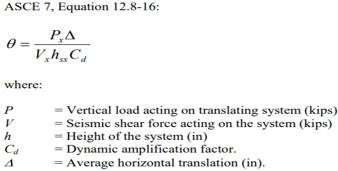
Flexible diaphragm deflection doesn't necessarily have a hard limit as far as I'm aware (whereas overall building drift limits have hard limits), but there are other considerations such as P-delta effects on the gravity and lateral systems. See ASCE 7 "Stability Coefficient". Another consideration is building separation when you have buildings located close to one another.


Commentary from FEMA p-1026 Seismic Design of Rigid Wall-Flexible Diaphragm Buildings: An Alternate Procedure said:
One potential safety concern with large flexible diaphragms that have large deflections is the rise in
second order effects including P-Δ instability. As the roof translates, the tops of columns and walls also
translate, resulting in a leaning gravity system that generates additional lateral forces further
exacerbating the deflection.

One simple method to evaluate this concern is through the stability coefficient, θ, of ASCE 7-10 Section
12.8.7. Although this stability coefficient, θ, was not originally intended to be used to evaluate
diaphragm deformations, with some simple adjustments it is a useful tool to investigate the diaphragm
system stability under P-Δ effects.

This equation evaluates the relative magnitude of the horizontal load added to the lateral force resisting
system at the system’s maximum expected deformation. An increase of 10% or less (θ ≤ 0.10) is
considered tolerable under ASCE 7-10 without a more detailed investigation.

The vertical gravity load acting on the translating system, Px, has a component from the roof weight, Px
roof, and a component from the wall weight, Px wall. As indicated by the applicable load combinations, the
roof live load is excluded from the weight of the translating roof system. Because the wall’s center of
mass between the roof and slab on ground is only translating approximately half of the roof’s
translation, the Px wall may be computed as the upper half of the wall plus any parapet. The load factors
are 1.0 for this investigation.

It is worth mentioning here that diaphragm deflection is not included when evaluating the story drift
limits of ASCE 7-10 Section 12.12.1. These limitations on building drift were developed primarily for
the classic flexible frame system with a rigid diaphragm to prevent excessive distortion within the plane
of the frame or shear wall. In masonry and concrete tilt-up buildings, the vertical elements deflect very
little in-plane, with the bulk of translation occurring in the diaphragm. The story drift limits of the
building code do not apply to the diaphragm deflection.

Snipaste_2024-09-11_11-40-58_qd6mki.jpg
 
Status
Not open for further replies.

Part and Inventory Search

Sponsor