Continue to Site

Eng-Tips is the largest engineering community on the Internet

Intelligent Work Forums for Engineering Professionals

  • Congratulations pierreick on being selected by the Eng-Tips community for having the most helpful posts in the forums last week. Way to Go!

GD&T without concentricity

Jbeaker

Mechanical
Dec 30, 2024
1
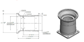
Please see the simplified drawing, I am omitting other dimensional and geometric tolerances for simplicity.

With the removal of the concentricity geometric tolerance in ASME 2018, I was trying to sort out how to ensure the inner diameters of the lens barrel are co-axial. A couple ways to do it, hole location, runout, and profile I think (controlling form and location).

Am I missing anything? I didn’t opt for a tertiary datum since I don’t really care about rotation. I want to ensure co-alignment between datum B (hole) and the other two holes.
 

Attachments

  • Simplified tol flange.png
    Simplified tol flange.png
    126 KB · Views: 47
Replies continue below

Recommended for you

Concentricity tolerance, as defined in Y14.5-2009, controlled location of median points derived from all diametrically opposed points on a feature surface relative to a datum axis. In vast majority of cases, this was not what designers really wanted to have controlled in their designs (from functional standpoint).

Position tolerance, as shown in your sketch, controls location of the axis of the two features (axis of the maximum cylinder inscribed within each of the two inner diameters) relative to datum axis B. Using planar datum feature A as primary ensures that the cylindrical position tolerance zones are perpendicular to datum plane A in the first place. If that's what you need from the design standpoint, position is the right choice.

Runout tolerance, in addition to controlling orientation of the holes relative to datum plane A and their location relative to datum axis B, will also control certain aspects of the features' form, i.e., circularity or cylindricity depending on the type of runout used.

Surface profile tolerance, assuming the size of the two diameters will be defined as basic, will control size, form, orientation and location altogether.

Again, the choice of geometric control should be primarily driven by the function of the feature.
 
OP
Let give a tip , typical multi diameter hollow shaft. Like this one will be surface ground on both faces. Held in pie jaws or magnetic mag. Operator will indicate inside diameters prior to grinding and during. That right he or she will be using a dial indicator to verify runout. True position as used in a CMM
Can be verified after. My choice is both internal bearing diameters must be coaxial.
I would make them A & B . Inside face perpendicular to A & B . As bearing will be held square.
 
Surface profile tolerance, assuming the size of the two diameters will be defined as basic, will control size, form, orientation and location altogether.
pmarc,

Can I use profile with dynamic profile modifier along with plus minus size ?
I am trying to use the size of the two diameters as plus-minus (+/-) and not BASIC.
So, only the nominal form/shape is basic and not its size for those two diameters (the size will stay plus-minus) you are talking about in the replay.
 
Last edited:
pmarc,
Looking at figure 11-38/ 2018 standard if Ø20 and Ø62 are direct toleranced dimension (plus minus) how the interpretation of the dynamic profile callout is changing?
Why the assumption is that if profile is used on a feature of size (such as those two diameters) then those diameters shall be basic? I am not really sure I agree with that.

Could you, please, clarify my dillema
 
Greenimi,
Let's consider profile (dynamic or static) on a cylindrical direct-tolerance-dimensioned feature. One could imagine it is like a combination of a directly toleranced diameter with total runout (if coaxial datum axis is referenced) or cylindricity (if no datums are referenced). But in fact it is simply undefined because there is no "true profile" (basically dimensioned surface) to base a static profile tolerance on or as a starting base for a dynamic zone that could "progress".
 
profile of surface is great way of dimensioning. how ever in a hollow shaft the operators have to verify their size with a bore gage , air gage or similar. and size of diameter is used. generally plus or minus tolerance for bearing diameters.
depending on the precision required.
profile of surface is used on surfaces that the best method is a CMM.
 
Let's consider profile (dynamic or static) on a cylindrical direct-tolerance-dimensioned feature. One could imagine it is like a combination of a directly toleranced diameter with total runout (if coaxial datum axis is referenced) or cylindricity (if no datums are referenced). But in fact it is simply undefined because there is no "true profile" (basically dimensioned surface) to base a static profile tolerance on or as a starting base for a dynamic zone that could "progress".
I don't buy it. Sorry.
The diameter does not have to be basic diameter and yet the profile could be used.
Profile tolerance could be applied to a feature for which not every characteristic is defined with basic dimension.
Fig 11-19/2018 is just an example of such. It is shown on a cone, but could be very easy seen as a cylinder (zero basic implied angle)
Basic dimension is just the form/shape and not its size.
And profile contains the dynamic profile modifier hence I see no reasons (unless you prove me otherwise) why cannot be a valid callout.
 
Greenimi,
In fig. 11-19/2018, where profile is applied to a cone, the tolerance zone is constituted by two coaxial conical boundaries with a fixed included basic angle - which is a "static" (non-adjustable) structure that can only be extended length-wise if needed (or be considered infinite, from an apex to an unlimited large end diameter). If the actual end diameter 30 +/- 0.2 in fig 11-19 exceeds the maximum or minimum limits, the profile tolerance requirement may still measure good (and only that size requirement on the end face would make the part fail). So essentially, there is still a fully defined and rigid/fixed "true profile" as a basis to the tolerance zone in that example. On the other hand to control a cylinder with non-basic diameter with a profile tolerance, you can't use a fixed, non-adjustable tolerance zone structure like you would for a cone, in the first place. You could say "Ok, but that's why I'm using the dynamic profile". Yes but, if you read the paragraphs in the standard, even the dynamic profile's zone is based in a way on the true profile - it is permitted to progress "normal to the true profile" as specified in 11.10, that is why it used as a refinement and not as stand-alone in all examples and even defined as one: "When it is desirable to refine the form but not the size of a considered feature that is controlled by a profile tolerance, the dynamic profile tolerance modifier, Δ, may be applied to a refining profile tolerance..."

Also, what would be the difference between a "static" and a dynamic profile tolerance, when a cylinder's diameter is directly toleranced?
Earlier you mentioned figure 11-38/ 2018, Ø20 and Ø62 - if those diameters would be directly toleranced, what would be the role of the top 0.25 segment? Notice that the bottom 0.15 dynamic segment controls form, location and orientation.
 
As a consequence of a poorly formulated means of application, it certainly seems that a dynamic profile tolerance zone modifier applied to a profile tolerance controlling the form of a cylinder with a directly applied tolerance is allowed.

It's redundant with cylindricity, but that may be an argument for eliminating cylindricity.

True profile only requires some basic dimension such as basic dimension of size or basic angle to establish the true profile; basic angle is covered under 5.1.1.2 Basic Dimensions.

Note that it doesn't say it has to be a refinement of an existing profile tolerance, just used in order to allow form to be controlled independent of size.

Instead it says :

"The actual feature shall simultaneously be within the dynamic profile tolerance zone and any other applicable tolerance zone."

Not a fan of dynamic profile - it appears applicable to practical problems no one has, though it does provide a box to check for CMM operators.
 
On the other hand to control a cylinder with non-basic diameter with a profile tolerance, you can't use a fixed, non-adjustable tolerance zone structure like you would for a cone, in the first place.

Burunduk,
I agree with your assessment except for the above text.
In my opinion in fig 11-20 diameter datum feature A could still be direct toleraced feature dimensioned with plus-minus. I don't think "A" shall be basic.
The second segment (fig 11-20) is not affected by this. Why would it? I am not understanding.

Earlier you mentioned figure 11-38/ 2018, Ø20 and Ø62 - if those diameters would be directly toleranced, what would be the role of the top 0.25 segment? Notice that the bottom 0.15 dynamic segment controls form, location and orientation.
That's exactly my point. Why "my proposal" would not be valid if a regular feature of size is dimensioned with plus minus ?
So if the top 0.25 segment is removed and only the bottom segment is kept (along with plus-minus diameters) why this option you consider illegal?


Notice that the bottom 0.15 dynamic segment controls form, location and orientation.
I agree with this. So, now you have a FEATURE with all its characteristics fully defined. SFOL (size, form, orientation, location)


Could you, please, clarify my follow-up questions?
 
As we can see GD&T is not perfect.
And interpertation by the authors does have flaws. Just as every detail in life make it simple. And easy to decipher.
 
Concentricity, as defined in previous ASME and ANSI standards is not what you think... not interpretated per the word definition "Concentricity". I would strongly recommend that you review the applicable standards for the interpretation of Concentricity not the dictionary.

Position tolerances, as you have specified achieve coaxiality (Concentricity) between cylindrical features.
 
Greenimi,
In figure 11-20 datum feature A is not controlled by the profile tolerances, it is used to obtain the primary datum for the profile tolerances. It could be of any diameter and any size tolerance and it's size would not affect any of the 2 segments of the profile tolerance, since the profile tolerance zones are only constrained coaxially to the axis of datum feature cylinder A (axial location is set by the planar datum feature B).

So, now you have a FEATURE with all its characteristics fully defined. SFOL (size, form, orientation, location)

The difference between the dynamic and static profile controls is all about the relationship of the tolerance zone to the true profile, and in my opinion you need a rigidly defined true profile for both. For the static (default) tolerance, the zone is fixed to the true profile, while for the dynamic one it is allowed to "progress from" it, as the standard puts it. If you don't have something basic to fix a tolerance zone to, you don't have that same something to "progress from" either. Could you have a static profile tolerance for a directly toleranced diameter of a cylindrical feature?
 
Last edited:
to me it's , on a flat pattern easier to call out a diameter plus or minus, with true position. mmc. that's it. profile of a surface should be used on irregular surfaces. which is the easiest way to measure.
on hollow shafts and no what runout or total runout is supream
.way over thinking this.
 
"Concentricity is that condition where the median points of all diametrically opposed elements of a surface of revolution (or the median points of correspondingly located elements of two or more radially disposed features) are congruent with a datum axis (or center point)."

Concentricity
noun
the quality of having the same center (as circles inside one another)

The first is a bit more descriptive, but otherwise they describe the same situation. The reason for the first one is to more plainly accept more than circles.

Is that what you think or is there something else that is concerning?
 
easiest way to verify concentricity is just as runout. between centers or located on datum, and spin the shaft , and verify with dial indicator. same as verifying run out. to check concentricity, it is the same as total runout. verify runout the entire axis of diameter. real world application.
 
easiest way to verify concentricity is just as runout. between centers or located on datum, and spin the shaft , and verify with dial indicator. same as verifying run out. to check concentricity, it is the same as total runout. verify runout the entire axis of diameter. real world application.
With the only difference that parts rejected by runout COULD have been good per ASME's former concentricity (talking about 2009 versus 2018)
So, if concentricity was TRULLY functional requirements (highly unlikely however) then you would reject good parts. And no one wants to reject good parts
 
With the only difference that parts rejected by runout COULD have been good per ASME's former concentricity (talking about 2009 versus 2018)
So, if concentricity was TRULLY functional requirements (highly unlikely however) then you would reject good parts. And no one wants to reject good parts
If runout was the functional requirement then concentricity would be the wrong characteristic to control. On the other hand, if concentricity is the functional requirement runout could reject usable parts. Now that concentricity and symmetry are gone, there are no equivalents for them.
 
not really because the shop and inspection dept. and the customer would all agree to . and this would be the best method since it was better than was asked for. never became an issue. and since it was stream lined it saves cost.
 

Part and Inventory Search

Sponsor