Enrico Urru
Bioengineer
- Aug 13, 2023
- 19
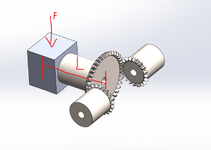
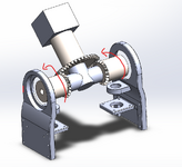
I am trying to determine the torque required by the two pinion bevel gears to move the bigger bevel gear (when the pinion gears rotate in the same direction), like in a differential mechanism. The driven bevel gear has a load on its end. Being the driven bevel gear horizontal it exerts the highest torque on the pinion gears. I would like to know if my calculations are correct. Assume pressure angle on gear teeth phi=20°, Rd=radius driven, Rp= radius driven, Td= torque drive, Tp= torque pinion, L = distance from center weight to face of driven gear, F=force of the load. I uploaded a picture of the set up.
The torque of the driven gear on the pinion is Td = F*L*cos(phi),
and the torque on the pinion to balance the driven gear with the weight is Tp=(Rd/Rp)*Td
The torque of the driven gear on the pinion is Td = F*L*cos(phi),
and the torque on the pinion to balance the driven gear with the weight is Tp=(Rd/Rp)*Td