Continue to Site

Eng-Tips is the largest engineering community on the Internet

Intelligent Work Forums for Engineering Professionals

  • Congratulations SDETERS on being selected by the Eng-Tips community for having the most helpful posts in the forums last week. Way to Go!

Profile tolerance unless otherwise specified - WRT Datums vs no datums 1

Frokilin

Mechanical
Feb 6, 2025
15
Hi,

I have read some post but I didn't fin a clear answer for this question. When you have a drawing with datums defined, and a general note saying "Unless otherwise specified profile tolerance of: "
What is the difference between having that surface profile called out back to datums or called out to no datums?
Besides having those surfaces better controlled, is there any other reason?
Thanks
 
Replies continue below

Recommended for you

It's not arbitrary; one simply has to look at how the surface (well, line) is related to the datum. And in that case it's not a basic dimension, so we are to understand that it's doing the lower-level control of orientation. That's the specific indication that you're looking for.

I used this example in some past discussions in the forum, so I'll use it again here. What if the surface with the line profile callout was nominally coplanar with datum feature A? Would then a directly toleranced zero dimension need to be applied to accomplish the similar effect as in fig. 11-32? Why wouldn't someone "just" use the approach shown in fig. 11-31 instead, where the line profile FCF explicitly informs everyone, including software, without the need to search all over the drawing for the related +/- dimension, that the datum feature references shall only constrain the rotational degrees of freedom of the line profile tolerance zones? Why couldn't the same approach be used in fig. 11-32 to avoid the controversy?


Garland23: I'm sure that you agree that if the symbol in Fig. 11-32 were profile of a surface, it would be identical to using the angularity symbol.

If the symbol in Fig. 11-32 were profile of a surface, I would strongly recommend changing it to parallelism to avoid the exact conversation we are having now. As a matter of fact, this (the use of the parallelism symbol instead of profile of a surface) would be the direct indication that the FCF is not to control location and I doubt that anyone, including software again, would have any issues with that.
 
I'll disagree a bit. Paragraph 3.68 defines true profile as requiring basic dims to define the profiled feature itself. It does not mention anything about the feature's relationship to any datums.
If a DRF is imposed but the location dimension to the profiled feature is not basic, then it controls orientation (with the angle being implied basic).
There is actually no disagreement.
I was answering on OP's question "Where in the 2018 standard implies that the surface profile controls location only when there is a basic dimension?", and that's what the true profile definition quote was for. You can have an un-located true profile if that is what you need. But if you want a located true profile, you need basic location (on-drawing or from-model) and the basic location dimensions would be part of the true profile definition just like the locating dimensions of a true position.

And I think that this state of affairs is what provided the possibility to create the 11-32 example, which I personally can't stand. I think it doesn't provide any useful ideas. It would be better to specify parallelism or angularity on EACH LINE ELEMENT note basis relative to A,B than a crippled profile. I view profile as first and foremost a location control for surfaces because that's the only direct and meaningful way to locate surfaces (non-size features). Using it like they did in 11-32 is like using position to control the perpendicularity of a single hole to the surface it's designed normal to. Also, there should be no functional reason to do what 11-32 shows. The directly toleranced height suggests some kind of fit requirement with the mating part, which normally implies that the 2 sides of the regular FOS have equal significance and no sensible reason to use one of the sides as a datum feature for controlling the orientation of the other.
 
Last edited:
Refloating this
The model is considered basic. This should be part of the default profile tolerance note [edit] along with ALL AROUND after the profile FCF [/edit].
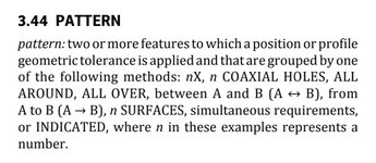
Theoretically, the part could have no datums at all and every feature of the part, including the datum features, might be controlled with a general profile with no datums from the general note, but then a philosophical question might be asked if this way of defining profile requirement would technically be a pattern/group creation mechanism, thus if it would be "strong" enough to impose mutual relationship between the features. Note that the definition of pattern given in para. 3.44 in Y14.5-2018 does not list "datumless-profile-specified-in-general-note" as a grouping mechanism. So to mitigate the risk, the general note would need to clearly say that the profile requirement applies to all part features simultaneously.

In regards to that, wouldn't the para. 11.3.1.5 in Y14.5-2018 cover the all over? It doesn't specify to say "all over" when you place the note in the drawing general notes?

"All Over Specification. A profile tolerance maybe applied all over the three-dimensional profile of a part UOS. It shall be applied in one of the following ways: c) place the profile tolerance requirement in the general tolerance block or general notes"
 
  • Like
Reactions: ewh
Frokilin,
I don't think this would solve the problem I described and you quoted.

Imagine that the general note is like this:
UNLESS OTHERWISE SPECIFIED, |PROF|.04|.

(Notice that, according to the problem statement, I did not specify any datums in the profile FCF.)

So it is rather clear that this note applies to every surface that doesn't have an "otherwise specified" control, but the problem remains as the note, due to the fact that the FCF has no datums referenced, doesn't clarify whether these surfaces should be treated as a pattern of surfaces (that is, all surfaces are tied with each other per their mutual basic relationship) or individually.

Therefore, to clarify, the note should rather look like this:
UNLESS OTHERWISE SPECIFIED, |PROF|.04| SIMULTANEOUSLY
or something to that extent.
 
Without "SIMULTANEOUSLY," the clear and obvious default interpretation is they depart each other into space like confetti fired from a cannon. /s

Why did ASME redefine the word "pattern" away from "duplicates" or "repetition" to instead mean "group"?

Oxford dictionary has this:

pat·tern
/ˈpadərn/
noun
1.
a repeated decorative design.
"a neat blue herringbone pattern"
Similar:
design, decoration, motif, marking, ornament, ornamentation, device, figure
2.
a model or design used as a guide in needlework and other crafts.
"make a pattern for the zigzag edge"

Notice that the second definition applies to a model or design that is used as a guide to duplicate that model or design in a different medium.

From Wikipedia:

A pattern is a regularity in the world, in human-made design, or in abstract ideas. As such, the elements of a pattern repeat in a predictable manner.

There is nothing certain to be regular about an abstract group of surfaces of different shapes, sizes, and orientations.

I get that it must have originated with references to an array of identical holes, a "pattern of holes." However, that vocabulary isn't appropriate to all the other uses that ASME Y14.5 puts it to to avoid changing the word from "pattern" to "group" in all the other places in the standard.

Whatever Tandler is third hand supposed to have said - either he's wrong about "SIMULTANEOUSLY" or whoever may be misreporting his feelings is.
 
ALL OVER could probably work as well.

In my mind, SIMULTANEOUSLY sounds more straightforward and provides more flexibility, but I understand others may see it differently.
 
UNLESS OTHERWISE SPECIFIED covers the part. It makes a single group of all surfaces that are have no other specification.

The implementation problem is if those UNLESS OTHERWISE SPECIFIED surfaces are not used as datum features.
 
UNLESS OTHERWISE SPECIFIED covers the part. It makes a single group of all surfaces that are have no other specification.
UOS doesn't imply that the control mutually locates and orients the considered features. It only tells you which surfaces are under that requirement, but the requirement could apply to each surface individually. Seperate features are mutually controlled by profile or position only if they are grouped as a pattern and basic dimensions connecting them are given in one way (drawing) or another (model).

1000021057.jpg

No mention of UNLESS OTHERWISE SPECIFIED in that definition.
 

Part and Inventory Search

Sponsor