Continue to Site

Eng-Tips is the largest engineering community on the Internet

Intelligent Work Forums for Engineering Professionals

  • Congratulations IDS on being selected by the Eng-Tips community for having the most helpful posts in the forums last week. Way to Go!

Datum callout question 2

SeasonLee

Mechanical
Sep 15, 2008
918
I have some questions about this print, and I tried to make some changes as shown below. The reasons for making these changes are:
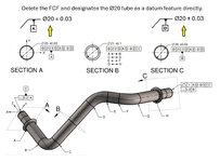
  • The common datum(A-B) is constructed after the individual feature is designated as the datum feature.
  • The existing DRF refers to the datum feature itself, normally we will consider it as a coaxial part, but here is a multiple skewed cylinder.
Datum callout.jpg
Do you agree with the changes on the datum callout? Please correct me if I am wrong here.
Thanks for your help.

Season
 
Last edited:
Replies continue below

Recommended for you

MMC (for qualfying the datum feature)......RMB (for referencing that datum feature) is also what the runout results at.
So are you saying you are OK with it just because it is illegal to reference a datum at MMB for runout? But the datum feature qualification could be RMB...
I am okay with both schemes shown in my replay above (green scheme and dark red scheme). I only have hard time to explain to people what is the logic behind the "combo". Why someone would want to have MMC (speaking of the green scheme) for qualifying the datum feature (in this case Ø zeo at MMC) and call this feature: datum feature A
AND THEN
when the 8mm hole is defined and datum feature A IS USED as primary someone would NOT use it as MMB but use it RMB.
What is the physical reality of such approach?

Or if someone would decide that the defintion of datum feature A is functionally RFS (considering Ø value bigger than zero) and when this newly created datum feature A is used to define the Ø8mm hole, we will use this A at MMB (modified at MMB).

Both cases are legal, but the explanation on why those "combo" are a good functional ideas.

Regarding runout, basically yes. I am okay with this inconsistencies because "the standard say so" (and runout cannot be modified neither MMC neither MMB). The runout is much easier to defend because again "is it's definition" per the book.
 
Last edited:
Just my humble opinion
It really depends it's fit form and function.
It is required for assembly
Or what is the designer want.

RMB or RFS is usually for precise or press Fitts.
MMC or MMB there wiggle room to assemble.

First case is more cost and there will be higher scrap rate.
The second will accept more parts and will assemble.

I love true position for holes. Only way to go.
Precision shafts where MMB is useless because
The tolerances are so tight. And precisely for
Where precision is required. To eliminate vibration, due to excessive runout or out of balance.

On assemblies where there no issue them MMB
OR MMC IS PERFECT
 
Actual minimum material envelope is created from inside the material. It "touches" the low points.

And so I make my point. The standard is written to maximize confusion.

LMC AND MMC are developed the exact same way, approaching the same material surface from opposite sides, but the description in the standard obliterates that similarity and fails to emphasize the difference.

Use INTERNAL MATERIAL SURFACE CONTACT ENVELOPE and EXTERNAL MATERIAL SURFACE CONTACT ENVELOPE.
 
"Both cases are legal, but the explanation on why those "combo" are a good functional ideas."

This is not a forum for explaining good functional ideas. This is a forum for legal language analysis without regard for applicability.

To understand good functional ideas one needs to examine the full tolerance loop and the range of variations and functional consequences of the applied tolerances and expected variations.

The way that General Dimensioning and Tolerancing (thanks for making that point Burunduk) is taught is to never evaluate those full tolerance loops because those are computationally expensive. And to never ever look at the functional consequences because those involve external functions - things like lubricant film thickness, stress and strain due to applied loads during assembly, cases were the "envelopes" do not represent actual mating conditions. Instead the instruction is how to add drawing decorations and make some primitive hole clearance calculations. Notice the lack of practical applications in any General Dimensioning and Tolerancing instruction, ones that start with a functional analysis and then back-calculate the controls necessary to meet them.

Most examples are geared to showing how to make life easier for CMM operators; some, like LMC and LMB, are nearly impossible for anyone without a CMM to evaluate if there is any form variation.
 
I only have hard time to explain to people what is the logic behind the "combo". Why someone would want to have MMC (speaking of the green scheme) for qualifying the datum feature (in this case Ø zeo at MMC) and call this feature: datum feature A
AND THEN
when the 8mm hole is defined and datum feature A IS USED as primary someone would NOT use it as MMB but use it RMB.
What is the physical reality of such approach?
Would you have an issue with A at RMB in the positional FCF for the 8 mm hole and instead of the datumless position of 0 at MMC for qualifying datum feature A, a Continuous Feature modifier aligning the two separate portions of the 16d9 diameter? It would mean exactly the same, only expressed by different symbols. What I am saying is that it is not necessarily a bad idea to have a size-adaptive tolerance for a datum feature of size and then calling out that datum feature at RMB. Even rule #1 alone is essentially a size-adaptive form tolerance (just having some "dia. whatever+/- whatever" is the same as having "dia. whatever+/- whatever " modified by circled "I" and then a derived median line straightness of 0 at MMC).
 
Burunduk and all,

Did 2018 clarify how to simulate a pattern of features at RMB? I know there were some issues in a previous revisions.
 
Question for you all what does RMB
Do or not do that RFS all ready does?

I get MMB it can be precisely used for intricate designs.

I get MMC it works very well for hole patterns.
On the onset using the same symbol for MMC and MMB was not good. It literally confuse
People. Until more training was available.

Profile of surface for tapers or irregular surface is the way to go. But on simple geometrical
Parts or component one has to walk the fine line.
One author on GD & T stated, even thou MMB symbol is on a datum in FCF , IT CAN BE IGNORED, on case by case drawings.
In my case I could do most of the time to simplify interpret for my machinist , and I don't get a lot of questions. And I all ways carried a red pen if I had to alter my drawings for process improvement.
I took my blinders off and had an open mind.
Rolled with punches. Now it's not but it is the designers responsibility to understand manufacturing, productivity, and unspection.
After a few years under their belt under stand this. I run into drawing were just not easy built because of how it was designed. Unbelievable
The tolerance held on old designs 50 , 60 ,70 years ago. With old style manufacturing was tough as s#@#*** . But skill set could manufacture it.
 
So, you are asking about RMB (the datum feature material boundary modifier), not about RFS (for the mutually locating position tolerance specification).

ASME Y14.5-2018 states:

" 7.12.4 Pattern of Features of Size RMB
When RMB is applicable in a feature control frame to common datum features of size used to establish a single datum, the true geometric counterpart of each feature shall be fixed in location relative to one another. The true geometric counterparts shall expand or contract simultaneously from their worst-case material boundary to their LMB
until the true geometric counterparts make maximum possible contact with the extremities of the datum feature(s). When irregularities on the feature(s) may allow the part to be unstable, a single solution shall be defined to constrain the part "

It's two coaxial (in the discussed case) datum feature simulators, and both simulators must be brought to the condition of max. possible contact with the actual datum features.

Basically I am asking what the highlighted text means ? (described for example in the context of two or more holes)
Or in the context of fig 7-17: Am I correct that as long as one simulator stops contracting then the other simulator shall stop contracting too (in the same time)?
For me it is still very muddy. I am not understanding what means "maximum possible contact" ?
As has been posted before. Usually applies to flimsy parts that be held in fixture. Then restrained by means of clamping. Held in place
To maintain contact of the important surfaces.
Then if passes its acceptable. Such as the tube assembly as the original OP post.
 
Question for you all what does RMB
Do or not do that RFS all ready does?
...
One author on GD & T stated, even thou MMB symbol is on a datum in FCF , IT CAN BE IGNORED, on case by case drawings.
...
RMB is what is being implemented when MMB is ignored. On the drawing, it is indicated by not using the circled M or L modifier following the datum reference letter in the feature control frame. As you know datum features are where you hold the parts at inspection and the holding devices are the "datum feature simulators" that are used to establish the measurement origin.
Inspecting at RMB basically means for a machinist inspecting his own work, or for an inspector, that they are supposed to use an adjustable-size device such as a chuck, a mandrel, a collet, a v-block (which is not really "adjustable" but can support a variety of diameters), or a vise for widths, as the "datum feature simulators". It means that at RMB the part is held firmly at inspection and it means a more stringent check. Because unlike in MMB (MMB uses fixed size devices to simulate the datums), you don't have any play available between the part and the fixture when inspecting features. MMB is more forgiving because for example, if you are inspecting a hole that deviated from its true position quite a bit, you can move the part a little relative to the fixture simulating the datums to make that hole pass. You don't have that with RMB.

That's why the GD&T author you mentioned said MMB can sometimes be ignored. You won't have any out of spec parts passing when implementing RMB even if the specification is at MMB. However if the RMB inspection rejects a part, an MMB check could possibly save it from scrapping.
CMMs are known (or at least used to be known) to have difficulties with reproducing the "play" effect of MMB. So CMM operators could sometimes ignore the MMB and then the inspection is a bit over-restricting, but it is on the safe side as to not having any bad parts pass. For manual inspection, MMB (and MMC) is often very convenient and provide the extra variation that is allowed per design.
yes I under stand that. but it requires a functional gage or CMM. MMB.
whIle that sounds straight cut
and straight forward. actual hardware has complex issues. on simple hardware like a washer is yes very simple. simple truth is
there surfaces that have to be machine precise for tooling. while it can beI some times simple on complex parts.
a straight forward high production cnc turn and milled part with no heat treat , or post heat treat, coating, or dimensions have to be held . with mmb.

an example would be parts that require case hardening on gear teeth, minor diameter, major diameter. teeth profiles. I have to hold final hardness on these surface 60 HRc or micro harness equivalent.
while machining these attributes all can be held precisely. .0015 inch runout, ttce, tce,
profile tolerance. .0005 inch max.
no issues. before heat treat.
Precision ground ring gears are a PITA to
hold roundness. after heat treat. special tooling has to designed developed to maintain roundness while case hardening.
at high temperature.

if the the roundness is not held .007 inch
or less, the parts are scrap.
then afterward post heat treat the ring gears
the faces have to be surface ground flat for toolng within .0005 flatness.
have to be ID grind for tooling. held within .0005 tolerance on the inside diameter.

then an arbor has to be designed and fabricated. ring gears are mounted on the arbor , then the od is precisely ground.
all for tooling. then pot fixture has ti be design and fabricated. ring gear is installed
this fixture for final gear grind.
MMB here is useless.
the reason is if the teeth don't clean up
properly. or grind the teeth case under spec.
scrap.

this is only one example.
these are high risk parts. and have
high scrap rate. but it has to be quoted in.
if a house tries to fabricate these parts.
with out experience expect a 75% scrap rate.
and nothing in ASME will help them.
 
Last edited:
Do you mean .0007?
What is the tolerance for the diameter?
after heat treat not finished ground , gear teeth will have .005 stock per surface.
if the measurement between wire for the gear. out round of the gear p.d.

finished ground
, gear teeth profiles have a very tight modified profiles.
.0003, .0004 inch.
tight tce and ttce
 
yes I under stand that. but it requires a functional gage or CMM. MMB.
whIle that sounds straight cut
and straight forward. actual hardware has complex issues. on simple hardware like a washer is yes very simple. simple truth is
there surfaces that have to be machine precise for tooling. while it can beI some times simple on complex parts.
a straight forward high production cnc turn and milled part with no heat treat , or post heat treat, coating, or dimensions have to be held . with mmb.

an example would be parts that require case hardening on gear teeth, minor diameter, major diameter. teeth profiles. I have to hold final hardness on these surface 60 HRc or micro harness equivalent.
while machining these attributes all can be held precisely. .0015 inch runout, ttce, tce,
profile tolerance. .0005 inch max.
no issues. before heat treat.
Precision ground ring gears are a PITA to
hold roundness. after heat treat. special tooling has to designed developed to maintain roundness while case hardening.
at high temperature.

if the the roundness is not held .007 inch
or less, the parts are scrap.
then afterward post heat treat the ring gears
the faces have to be surface ground flat for toolng within .0005 flatness.
have to be ID grind for tooling. held within .0005 tolerance on the inside diameter.

then an arbor has to be designed and fabricated. ring gears are mounted on the arbor , then the od is precisely ground.
all for tooling. then pot fixture has ti be design and fabricated. ring gear is installed
this fixture for final gear grind.
MMB here is useless.
the reason is if the teeth don't clean up
properly. or grind the teeth case under spec.
scrap.

this is only one example.
these are high risk parts. and have
high scrap rate. but it has to be quoted in.
if a house tries to fabricate these parts.
with out experience expect a 75% scrap rate.
and nothing in ASME will help them.
mfgenggear,
Yes, the gear example sounds like one where RFS controls and RMB datum referencing is appropriate.

The main thing is that for any part, using the default RFS and RMB or modifying to MMB and MMC (or LMB and LMC) should be done depending on fit and function.

For example, if the purpose is to locate a hole for interference fit, or transition fit, or an external feature that has to be located accurately for similar purposes, then RFS is the choice. Similarily if the datum feature interfaces accurately with mating part by interference or transition fit it better be referenced RMB to match that. But if a hole is designed to clear a mating component it should be controlled at MMC, and if the datum feature interfaces with clearance kept, it should be referenced MMB. For wall thickness preservation or for making sure there is enough machining allowance for the next production process, LMB and LMC.

Generally the idea is that when evaluating a produced part for "GD&T" requirements it should be pretty much like measuring it relative to and within it's functional assembly as if you have the mating parts to serve as fixtures and gages.

For everything to work, it should be the design engineer's expertise and responsibility to reflect and ensure the function of the part in the product definition documentation, but he or she should also be familiar with shop floor and inspection possibilities and limitations. It should be the manufacturing and inspection's expertise and responsibility to realize the product as defined and verify the requirements, but they also should be familiar with the function of the parts and aware of the considerations of the design.
All good
 

Part and Inventory Search

Sponsor