Eng-Tips is the largest engineering community on the Internet

Intelligent Work Forums for Engineering Professionals

‘Slabless’ concrete stairs 1

Status
Not open for further replies.

bugbus

Structural
Aug 14, 2018
498
0
0
AU
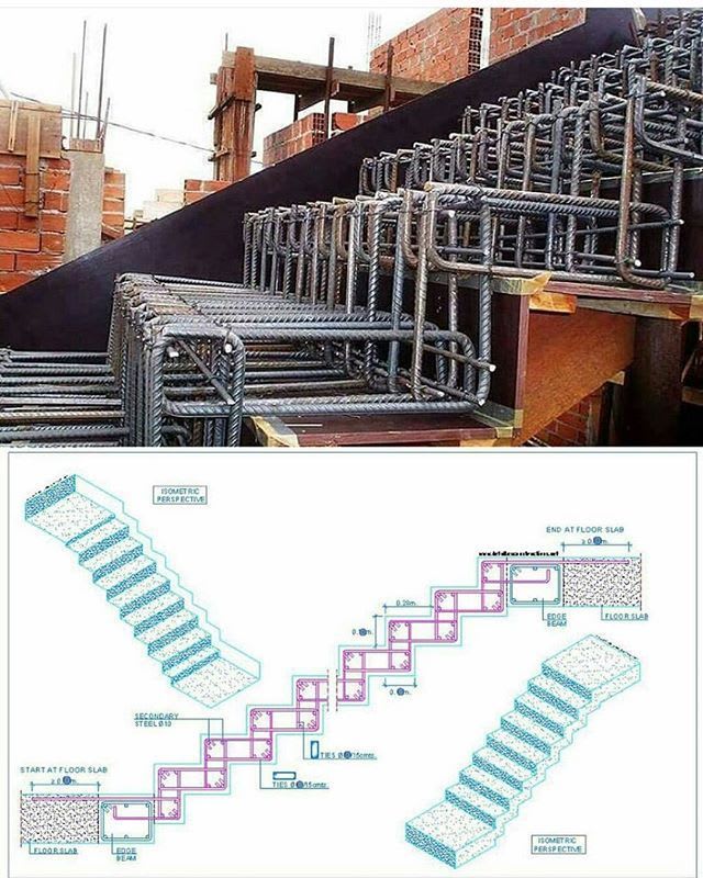
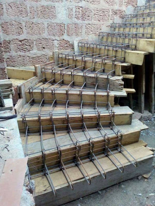
I have recently come across a number of photos from various parts of the world where it seems that slabless RC stairs are often used in buildings. Seems to be mainly in South America, Middle East, and Asia. See examples below. I’m wondering if anyone has had experience designing stairs like this and what the various design codes have to say about it? I am from a bridges background so I only have a little experience with stairs and this has usually been just the typical inclined slab with treads.

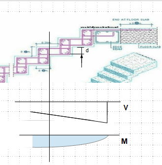
Apart from being quite elegant from an architectural perspective, I can’t help but think this seems like a pretty inefficient way of supporting a load at two ends. The flexural capacity relies on what looks like a fairly awkward anchorage of the rectangular links around the small transverse bars, with a diagonal strut in overlapping region of the adjacent links. However, presumably the numbers can be made to work with STM.

Any thoughts?

957D81DB-488A-448D-A550-4EE37BE25152_ywaek5.jpg


992EF29F-772D-44AD-9AFA-FE81716AADF2_k7ktez.jpg
 
Replies continue below

Recommended for you

MIStructE_IRE, I was tempted to post a few similar photos of failed stairs like yours but wanted to start off a little more impartial ;)

But I assume even a flat slab with the same thickness (50 mm?) as the above would have failed like that
 
Lol, sorry, i couldn’t resist! There are plenty of failed examples of this.

In theory it can work, deflection and sag can be an issue though. You could visualise the real length of the stair ‘slab’ as the straightened out length...which is going to be double the length of the actual stair span. So as a starting point the L/d should be proportionate to the straightened length, which may give a rather chunky looking side profile if it’s to be done right. That said, plenty of things stay standing by luck rather than design. If things actually fell down we’d all be well respected millionaires!

Its very inefficient and should cantilever out from the wall instead if possible in my view.

I’ve never designed one of these though. The closest I’ve done still had a hidden beam along the middle of the stair. So it looked like your photo from the side but you could only see the beam when standing underneath.

 
Do you include the DL of the reinforcing?

Rather than think climate change and the corona virus as science, think of it as the wrath of God. Feel any better?
-Dik
 
@MIStruct_IRE,

Straightened length s a bit of simplification that gets the message across, however rotation at each stepped joint and the consequent opening up of steps will add a lot of movement that is not strictly speaking flexural in nature. That's to say if the stepped joints don't simply fail...

@OP,

I will throw two more things into the mix (if you are not too discouraged by the apparent displacement performance):

1. Bar anchorage - from what I know most concrete codes do not allow for continual development of bar around a minimum bend diameter. This means that bars in your first photograph are at best half developed (at least on paper). The question is how are you ever going to fit a 10-diameter (typical minimum bend diameter for continual development of reinforcement) rebar bend through these folds?>​

2. Rebar vs concrete mass. Traditional concrete stairs are made this way for a reason - it is material efficient and doesn't take up much space.​

Ultimately I think that this sort of configuration can work if you must have it for aesthetic reasons, however by the time you are done sizing, detailing, and documenting it you will really wish that you had gone with the traditional configuration.

 
@captain_slow

On bar anchorage, I would have thought that the transverse bar in the corner of the bend would effectively anchor the link, in the same way that stirrups in a beam are effectively anchored over their full length by being hooked around the larger diameter longitudinal bars - although in the first photo the transverse bar is clearly a smaller diameter so this wouldn't comply with most codes.
 
Mainly a question of the sectional strength to resist the shear and moment, especially at geometry changes.

image_goizxj.png
 
Status
Not open for further replies.
Back
Top