Continue to Site

Eng-Tips is the largest engineering community on the Internet

Intelligent Work Forums for Engineering Professionals

  • Congratulations SSS148 on being selected by the Eng-Tips community for having the most helpful posts in the forums last week. Way to Go!

0 @ MMC vs. 0 @ MMB 2

Status
Not open for further replies.

weavedreamer

Automotive
Aug 1, 2007
279
0_MMCvs0_MMB_yx7ntk.png
 
Replies continue below

Recommended for you

I'd say it's a violation, since the hole has zero tolerance, regardless of its size. The datum's shift just says that you might be able to jiggle the part around, but the hole's axis must still be perfectly aligned.

Interesting idea about the zones, however.

John-Paul Belanger
Certified Sr. GD&T Professional
Geometric Learning Systems
 
weavedreamer,
May I know why you would want to apply a tolerancing scheme as shown on the picture on the right?
 
Per the explanation as I understand it, pmarc, the two dimensioning schemes should yield the same result.

On the left, Zone C would be the datum, regardless of feature size, while Zone A uses the 0.012 diameter bonus as the feature deviates from 20.045 toward 20.057.

Per the right illustration, Zone A would be the Datum with the 0.012 shift permitted as the feature deviates from 20.045 toward 20.057 while expecting Zone C to act, much as it would as the datum in the example on the left.

The obvious advantage is the more repeatable length avialable in Zone A to be used as Datum B.
 
Unless leaving the MMC modifier was a typo (right hand figure) it's a bad callout.

Besides that, these will not yield the same results. Only on perfect parts will that happen. Don't be surprised to see a significant difference.

John Acosta, GDTP Senior Level
Manufacturing Engineering Tech
 
PH and Pmarc -- I do see why he/she is asking.
In the first case the datum is always true (based on an expanding gage) and the variation on the toleranced feature causes a "fudging" from the zero (called bonus). In the second case the datum might be "fudging" (called datum shift), while the other feature is always true. In either case there is still some variation between actual axis and actual axis.

It violates the standard, but I'm trying to verbalize the reasoning of the question.

John-Paul Belanger
Certified Sr. GD&T Professional
Geometric Learning Systems
 
weavedreamer,

It seems to me that two schemes are exactly equivalent. In both cases, the surface in ZONE A must not violate a diameter 20.045 boundary concentric to the feature axis established from the surface in ZONE C.

If the two schemes are equivalent, then the "obvious advantage" you cite must not actually exist. I can't imagine any other possible advantages either. The major disadvantage of extreme strangeness remains.

I don't know whether it's a violation of the standard. However, using a tolerance of diameter 0.000000001 is certainly not, and would achieve practically the same result.


pylfrm
 
The zones aren't exactly equivalent, but both versions are legitimate.
 

powerhound (Mechanical) said:
Unless leaving the MMC modifier was a typo (right hand figure) it's a bad callout.

Besides that, these will not yield the same results. Only on perfect parts will that happen. Don't be surprised to see a significant difference.
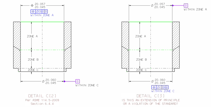
The MMC modifier was specified as MMB in conjunction with switching the Datum and Geometric callouts, to keep the bonus/shift with the same limit dimension.

Belanger (Automotive) said:
It violates the standard, but I'm trying to verbalize the reasoning of the question.
I did the two sketches, and did my best to lay out the virtual conditions to try to understand the reasoning behind the request.

pylfrm(Mechanical) said:
It seems to me that two schemes are exactly equivalent.
In both cases, the reasoning leads me to the same the same layout of the geometry.

I can't point to the specific "what" in the standard that it violates, unless I am looking at it, and just cannot articulate it.


3DDave (Aerospace) said:
The zones aren't exactly equivalent, but both versions are legitimate.
I'm coming up with exact equivalency. It is the legitimacy I am trying to ascertain.

Thanks, everyone, for the feedback.
 
Your example is a form of the property => A*B = B*A. There's not much in the field to identify equivalencies like this.

Are you expecting a phrase or paragraph from a standard that says you can't do this? What proof is required?
 
Perhaps the issue lies in how such a thing could be measured. Since there's no MMC modifier, you can't use a functional gage. You'd need a gage that is variable or something that outputs a number. So... how can any instrument verify a perfect part? (That's what the zero tolerance RFS means.) To what accuracy?

John-Paul Belanger
Certified Sr. GD&T Professional
Geometric Learning Systems
 
Same gage as is variable to adapt to an RFS datum reference.

I think the point is the gage for either case is the same.
 

Belanger (Automotive) said:
Perhaps the issue lies in how such a thing could be measured. Since there's no MMC modifier, you can't use a functional gage. You'd need a gage that is variable or something that outputs a number. So... how can any instrument verify a perfect part? (That's what the zero tolerance RFS means.) To what accuracy?
I think you just helped to trigger why I didn't see the fallacy in this earlier. If two features were related back to Datum B at 0 RFS, the simultaneous gaging would ignore the shift produced by an MMB callout between the two features. The two features would be stipulated to be zero tolerance RFS to each other, where 0 at MMC would permit tolerance as the features moved toward their LMC counterparts.

Even though the shift acts like the bonus in this singular relationship, they are different ways of regarding the relationships between the features in question.
 
Two (a little bit provoking ;-)) questions:

#1.
J-P said:
Perhaps the issue lies in how such a thing could be measured. Since there's no MMC modifier, you can't use a functional gage. You'd need a gage that is variable or something that outputs a number. So... how can any instrument verify a perfect part? (That's what the zero tolerance RFS means.) To what accuracy?
Assuming a hard gage is not used, for an undoubtedly legitimate |pos|0(M)|B(M)| callout, if the size of Unrelated Actual Mating Envelope (UAME) of toleranced feature equals its MMC size, and the size of UAME of datum feature B equals its MMC/MMB size, the toleranced feature must be perfectly coaxial with datum axis B, right? So does it mean that such actual part condition is impossible to verify?

#2.
weavedreamer said:
If two features were related back to Datum B at 0 RFS, the simultaneous gaging would ignore the shift produced by an MMB callout between the two features. The two features would be stipulated to be zero tolerance RFS to each other, where 0 at MMC would permit tolerance as the features moved toward their LMC counterparts.
What if the simultaneous requirement was overriden by use of SEP REQT note?
 
Any zero position tolerance with 'bonus' on either feature or datum has the same problem. If the part runs up to the limit it has to be perfect. But then using any non-zero tolerance has exactly the same verification problem when the variation approaches the limit allowed.

Read up on how the NIST verifies gage blocks and accounts for the fact that light is not reflected from the metal surface, but a fraction of a wavelength inside the metal, leading to different values than from mechanical measurements. The closer one gets the more variables need attention.
 
pmarc (Mechanical) said:
#2. What if the simultaneous requirement was overriden by use of SEP REQT note?
If the standard were to adopt |pos|0|B(M)|, any and all simultaneous gauging between two or more of such instances would have to mandate the SEP REQT caveat.

 
There are a lot of non-functional legitimate combinations that aren't proscribed by the standard. Dealing with them would make the standard very large indeed.
 
So you guys are saying that the 0 tolerance RFS (with MMB) is legitimate, per Y14.5?

John-Paul Belanger
Certified Sr. GD&T Professional
Geometric Learning Systems
 
Zero position tolerance at RFS to NOT per the standard. Logically it makes no sense as nothing can be perfect and must have tolerance to define how imperfect it can be. MMC must be used with zero position to gain tolerance from feature size change.

Regarding datum B at MMB: This is to the standard... but...I wonder, under what real-world design conditions would this dimension schema be used? I think its good for case-study but not much else. We have a "similar" condition with and assembly of a (rotating) turbine onto a shaft, where zone A and zone C are to be coaxial so the fit is uniform. We dimension zone B larger in diameter so it has clearance and is not part of the fit-up between the part and the shaft (at zones A and C). This is an RMB datum condition and not MMB, so shift it not allowed, but the application of MMB could be applied (as shown) depending on the function and fit-up requirements.

Certified Sr. GD&T Professional
 
3DDave said:
There are a lot of non-functional legitimate combinations that aren't proscribed by the standard. Dealing with them would make the standard very large indeed.

mkcski said:
under what real-world design conditions would this dimension schema be used? I think its good for case-study but not much else.

These two quotes pretty much sum up this argument, in my opinion. It's an intriguing thought but what's the real world use of the right side drawing that isn't legally expressed another way?

I don't think this is a legitimate callout for the following reasons:

1. There is no support for a 0 @ RFS geometric tolerance in the standard.
2. There is a legitimately supported way to achieve the same results. No need to get overly creative about it.


John Acosta, GDTP Senior Level
Manufacturing Engineering Tech
 
Status
Not open for further replies.

Part and Inventory Search

Sponsor