-
1
- #1
weavedreamer
Automotive
- Aug 1, 2007
- 279
Follow along with the video below to see how to install our site as a web app on your home screen.
Note: This feature may not be available in some browsers.
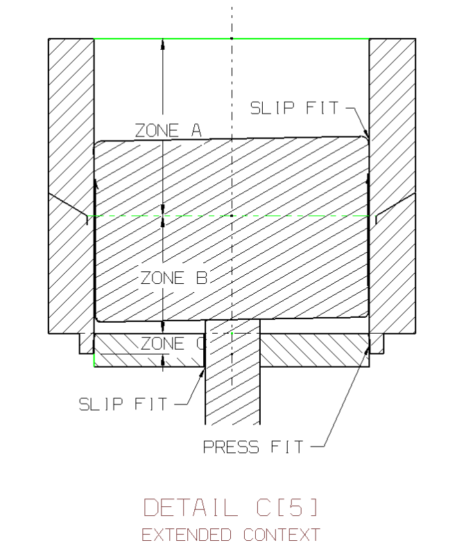
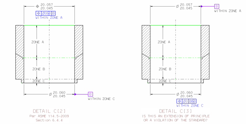
weavedreamer said:Specifying it as 0@RFS, effectively leaves it without a tolerance zone. This is the violation of the standard.
My wording didn't convey this well. Rephrase as:pylfrm said:The tolerance zone does not disappear, it collapses to a line. If the feature axis is coincident with the "tolerance line", then the requirement is met. At least this is how it's described in Y14.5.1-1994.
said:I'd say it's a violation, since the hole has zero tolerance, regardless of its size. The datum's shift just says that you might be able to jiggle the part around, but the hole's axis must still be perfectly aligned.
No -- it only leaves the zone without a tolerance with respect to the datum axis derived from a MMB datum feature.Specifying it as 0@RFS effectively leaves the zone for the feature axis without a tolerance.
![[smile]](/data/assets/smilies/smile.gif "[smile] [smile]")