Continue to Site

Eng-Tips is the largest engineering community on the Internet

Intelligent Work Forums for Engineering Professionals

  • Congratulations SSS148 on being selected by the Eng-Tips community for having the most helpful posts in the forums last week. Way to Go!

1-Center Beam Floor Support. (tile deflection) 5

Status
Not open for further replies.

EngStuff

Structural
Jul 1, 2019
81
This is one of those projects that I need major opinions on.

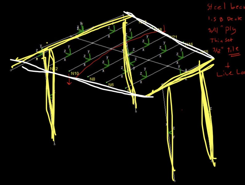
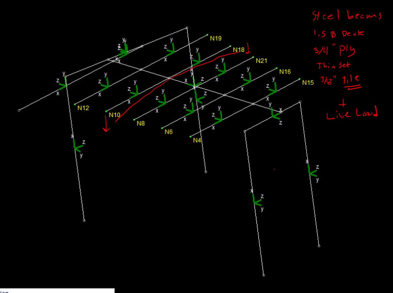
I have a Mezz. that will be considered a "stage floor" that will only be supported by 1 Beam. This beam will be an HSS member which will be supported by girders that are also HSS and HSS columns. the cantilever beams might be tapered plates or tapered W-shape beams with steel cladding or combination of both. Moment connections are everywhere including a fixed base. The floor is tile. [sad] see image below.

When it comes to deflection. Since we have both cantilever beams deflecting at their ends. At the center beam, I am worried about a tension strain on the thin set and tile(cracking). I think I will end up calling for a uncoupling membrane but that might not be enough. I am also worried about a "bump" at the center beam due to deflection on both sides.

I analyzed with full dead and live load. I also analyzed with full dead with skip live loading one each side.

My question is, what do you guys think I should hold the deflection to in this case? Also, is there anything I should take into account when designing this that I might not have thought of. Any pointers? I have admittedly not dealt with a floor like this.

Floor dead load will consist of
1. Steel beams
2. 1.5B metal deck
3. 3/4 ply
4. Thin set
5. 3/8" tile
6. Misc.
(uncoupling membrane?)

canti_tile_deflection_nipvig.jpg
 
Replies continue below

Recommended for you

This looks like a terrible idea to me. It will be very flexible with lots of vibration. Couldn't you run a beam from each portal frame knee and then rest the floor beams on those two support beams, then they would be simple span with much shorter cantilevers?

Jim

 
Jimstructures.

I did push for that, but it's a no. They are adamant due to esthetic reasons with this being located at a section of the building where they cannot have beams at those locations. It's also the reason why the cantilever floor beams need to be tapered.
 
Also, another thing that is on my mind. Deflection for tiles have always been used for floors that cause a "compression strain" on the tiles. In this case, we will see a "tension strain". Perhaps on the thin set, but that thin set will transfer the force onto the tile as well. Which it seems like regardless if we use an uncoupling membrane, it doesn't really solve that issue. Thus will cause cracking.
 
Ok....

I guess my doubt about the practical need for high torsion restrain connections expressed in this thread has been shown to be wrong.

Have you even considered torsion in the beam? Put all the live load on one side of the platform and you are going to need a hell of a HSS member for it to be stiff enough.

EngStuff said:
Also, is there anything I should take into account when designing this that I might not have thought of. Any pointers? I have admittedly not dealt with a floor like this.
Um.... Torsion, torsion, torsion! Forget beam deflection this likely where most of your deflection will come from. Watch what your modelling package is doing, it may not account for it and it WON'T account for it if you are putting symmetric loads on both sides.
 
human909.


human909 said:
Have you even considered torsion in the beam? Put all the live load on one side of the platform and you are going to need a hell of a HSS member for it to be stiff enough.

human909 said:
Um.... Torsion, torsion, torsion!

LOL yes definitely took torsion into account!

I designed for skip loading as well. Took torsion into account, I fixed all my HSS members. I will probably have end plates, then use an all around weld between the plate and the supporting members. Oh yeah these members are stiff LOL

human909 said:
Watch what your modelling package is doing, it may not account for it and it WON'T account for it if you are putting symmetric loads on both sides.

I used RISA 3D and created separate load combinations for the skip loading. I placed each load separately at each side of the cantilever beams.

I am not too worried about the strength of the members, I am really concerned about the deflection/vibration and tiles cracking. I think that will be the weakest link in the project.

My thought is, If I can design the connections to limit the yielding/deformation of the connection itself. Than my main concern would only be the main members themselves. They are definitely stiff members!


What is the use of the floor? I suggest to use ASD to keep everything away from yield.
 
You can do it... but your support beam has to be massive for torsional restraint... and you should change your flooring to vinyl... it's likely the only thing that will withstand the large deflections and vibrations. I should have added... it's a really bad design and idea in the first place. In my circumstances, I'd pass on the project... little good can come of it. Also should have added that the portal frames are also bad for sway... W24s might help...or cross-bracing

Rather than think climate change and the corona virus as science, think of it as the wrath of God. Feel any better?

-Dik
 

LFRD works, too... you just have to keep an eye on serviceability.

Rather than think climate change and the corona virus as science, think of it as the wrath of God. Feel any better?

-Dik
 
The cantilever beam has no redundancy, it is more on the safe side to use ASD, for which the reserve capacity is higher, and is known. But it's only my opinion/preference.
 
How about camber the floor beams for the effect of deal load plus a percentage of live load. The mono beam and its end connection will be quite massive/rigid in order to minimize the rotation due to unbalanced (skip) load.
 

It's not a safety issue... ASD and LRFD can accommodate... strength is only one of the criteria for design... and I find strength for LRFD, more consistent... but I've been using it (without incident) for 50 years.

Rather than think climate change and the corona virus as science, think of it as the wrath of God. Feel any better?

-Dik
 
dik said:
It's not a safety issue... ASD and LRFD can accommodate... strength is only one of the criteria for design... and I find strength for LRFD, more consistent... but I've been using it (without incident) for 50 years.

Yeah I too was confused but the comment about ASD. But its nature reserve capacity is less directly known as all the factors are lumped together. With LRFD you are using sensible and statistically based reduction factors on the loads and capacity assumptions of the structure. You still get two numbers which you can compare to give a "reserve capacity figure". (This figure often isn't quite linear, so if you really want the reserve capacity then you need to scale up your loads until you reach your limit.)

That said strength in most cases isn't a concern here. It is deflection.

I can see only two solutions;
-Slap the architect;
-or use ridiculously oversized members.
 

It can be done, and it's the type of project that I would like... just for the challenge (I haven't fully grown up yet)... everything would have to be beefier including the rigid frames at the end... if you have the funds... but there are issues about having a 100 psf liveload cantilevering from a beam... you could easily be looking at an HSS 24x24... just the time for the analysis and design would be substantial. If a project is unusual, I often don't charge for all the time I put into it... not this one.

Rather than think climate change and the corona virus as science, think of it as the wrath of God. Feel any better?

-Dik
 
dik,

I said "safe" was in terms of design philosophy of the two methods. Surely both have worked fine.

Below is a comparison of a cantilever beam design using ASD and LRFD. If I didn't make mistake (please check), the result indicates LRFD will yield the most economical cross section that satisfies both strength and deflection requirement, while the resulting ASD cross section is much stiffer. If we further look into torsion, it would be interesting to see which one is more preferable.

image_yuxmnw.png
 
Hehehhehhee...

Rather than think climate change and the corona virus as science, think of it as the wrath of God. Feel any better?

-Dik
 
Ok, so having suitably slapped the architect, and slept on a solution. I would perhaps consider:

1) Flat slab (with false ribs under if that’s what he wants to see... tell him they’re doing something..)

2) Perimeter (white) beams supported on cantilevered ‘goalpost’ portal frame beams (yellow) as shown below to remove torsion. Put in the middle beam anyway if that’s what he wants to see..

A974D60B-1023-4816-8700-E44CB216D26F_wgsxkm.jpg


For me, the current scheme as is, is asking for trouble.
 
I admit that the two results of the methods will narrow down quite a bit for I beams, and the added DL of ASD is added back to the equations. But for strength concern, the reserve capacity of ASD is clear.

IRE, Good idea.
 
Flat slab would be worse... IMHO.

Rather than think climate change and the corona virus as science, think of it as the wrath of God. Feel any better?

-Dik
 
Status
Not open for further replies.

Part and Inventory Search

Sponsor