Continue to Site

Eng-Tips is the largest engineering community on the Internet

Intelligent Work Forums for Engineering Professionals

  • Congratulations KootK on being selected by the Eng-Tips community for having the most helpful posts in the forums last week. Way to Go!

12' Retaining Wall Question 3

Status
Not open for further replies.

Sokka10

Structural
May 31, 2021
28
Hi everyone, after lurking around the forum here for a few years I finally made a profile. I recently broke away from the small structural engineering firm (almost exclusively light-frame residential projects) I was at to start my own firm. I hope to contribute a little back to the engineering community here since many of your answers have helped me on projects I've worked on. Anyway...

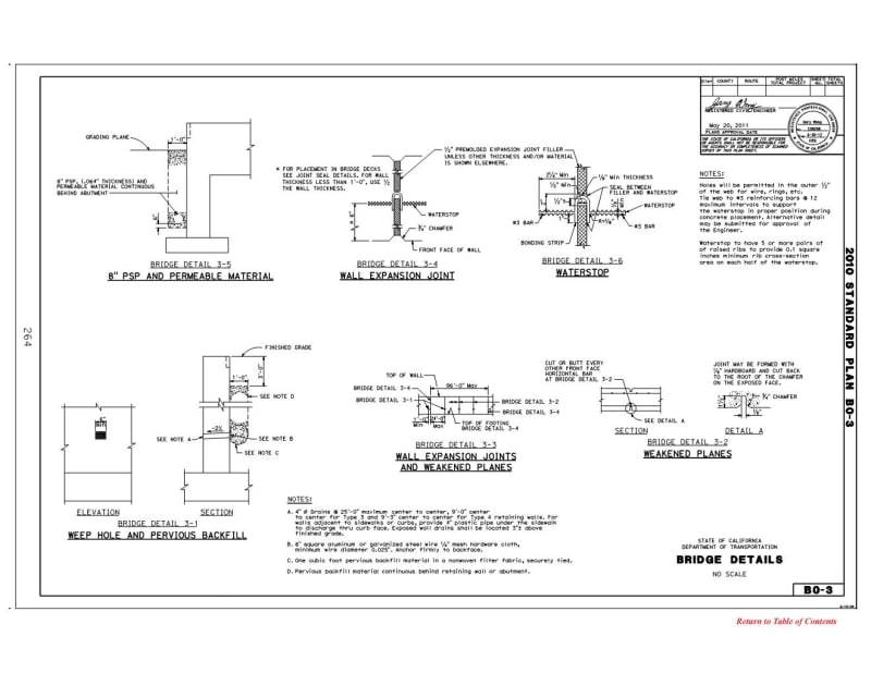
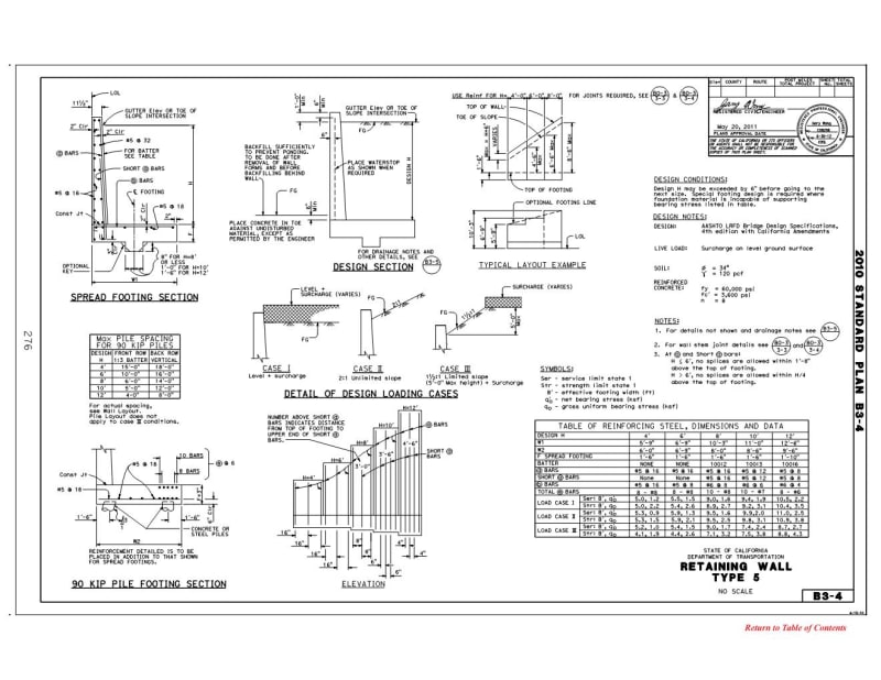
I'm designing a 12' tall retaining wall pretty much right up against the property line in the client's backyard. I have a geotechnical report for this one so I'm using all the values they gave me in the report. I have attached the design that I've come up with so far. I have two questions...

1) At what point does such a wide heel on the footing stop helping? Can I really count on a 7'-6" wide heel to act as one unit? Let's say I had a 20' wide heel, it seems obvious that at a certain point the heel is so far away from the wall itself that it's not doing anything to help with overturning, bearing, etc.
2) Are you aware of places in any relevant code books (IBC, ACI, etc.) that gives insights on drainage design for retaining walls? I feel confident in the drainage I have called out on the detail (drain rock, perforated pipe, etc.) but I'm wondering if there is any sort of standard to reference when designing for drainage?

Here's the link for the retaining wall detail: Link
 
 https://files.engineering.com/getfile.aspx?folder=db3968f4-30c5-45bf-856f-0e0e468212aa&file=Retaining_Wall_Detail.pdf
Replies continue below

Recommended for you

STrctPono said:
Are you using the extra dowels for added reinforcing only at the base as it looks like you are running them 3ft up the wall.
Yes, that's correct.
STrctPono said:
Sokka10, are there any other structures (house) within 12ft of this retaining wall?
No, the house is set back about 25ft from the wall.
dik said:
You might want to taper the wall from 12" at the base to 8" at the top.
Unfortunately where I'm at (Utah) tapered walls are never used for residential retaining walls. I can only imagine what the contractor will say if I give him a tapered wall design, but it wouldn't be anything good. And then he'd have another engineer design the wall for him lol.
wrxsti said:
i think retain pro prolly uses the 0.7 factor and told him his dev length is ok
Yes, that's exactly what I used to get a development length of approximately 9.5"

Ok so I've decided I'll go with a 10" thick wall based on everyone's comments. As far as the hooked rebar issue is concerned, I read through that entire thread that RWW002 linked to and now I'm more confused than ever. I've based my hooked bar embedment and hook extension straight from ACI, but it sounds like that is not adequate? Thanks for the suggestion of looking at CSRI.

 
@Sokka10 if youre getting 9.5" then you're prolly on a default of 3000 psi concrete strength
and that 9.5" still wouldnt meet the req for 12" thick base and 3" cov

also phamENG made an excellent point for providing above this value for such a critical
part of the design
 
Sokka10 said:
As far as the hooked rebar issue is concerned, I read through that entire thread that RWW002 linked to and now I'm more confused than ever.

You are not alone good sir. There are a few of these such threads where it's clear something is going on that I had never previously thought about (awesome!), but at the end of the thread the only thing I am sure of is that I had it wrong and still have it wrong (not so great...my prior false confidence made for better sleeps). KootK has a couple such wowzahs when it comes to reinforcing details especially as they pertain to moment connections.

Here have been a few of my takeaways from some of those threads that pertain to your situation (note: these are my takeaways and see above for the only thing I am sure of is that I don't really understand things. So take this with a mountain of salt):

A) Although reinforcing development length calculations could take into account more global concrete conditions, they pretty much dont. Meaning all the development length tells you is the length required for being able to achieve full yield of the bar based on local bond/bearing, not that adjacent concrete wont exhibit a failure prior to the yield stress occuring.

The way I've rationalized this is to think about a simple rectangular prism made of concrete with a single rebar developed into it with some portion of the bar sticking out. The prism is some distance larger then the development length of the rebar, and has an infinitely strong clamp at the end where the bar is not sticking out. Clearly if I pull the rebar to the point of inducing the bar yield stress, it wont break from the concrete. Well, because I've developed it after all.

But that doesn't mean I wont have a tensile failure of the concrete between the end of my rebar and the infinitely strong clamp. Surely that capacity would be governed by the concrete alone and dependent on the size of my prism (after all my tensile forced needs to be resolved somehow so it needs to go through that chunk of unreinforced concrete), but the development length calculation never took that into account!

In other words, it's not a develop it and forget it kind of world out there!

B) If you agree with (A) then it becomes clear you need to check for more global concrete failures associated with your bar layout. In the case of a moment joint, such as your retaining wall, turning the wall bars into the heel induces a uplift/tensile force at a corner of concrete that is incredibly weak. In other words, that area might fail!

KootK argues that turning the bars towards the toe induces a compression strut in the concrete. Plus you get the benefit of passing your bar under more confining concrete (passes through COG of the wall). Seems reasonable. Though compressive failure of the strut could still happen and adding upper matt is ideal practice to mitigate.

C) If you cannot develop your bar into the toe because it is rather small then hooking or using a trombone will work. If you want to hook the bar into the heel you can do so but must detail the opening joint such that steel crosses it to minimize the crack opening.
 
Draw yourself the moment diagram for the stem and footing and ask yourself “How does this work at the base of the stem?”

Retaining walls are relatively simple. You should do this one by hand before turning over the design to a piece of software.

Using the active pressure only is pretty optimistic. All other cases (at-rest, hydro, surcharge) significantly add to your loading. Be careful about skinnying the design down.
 
I’ve never really trusted weep holes to not get clogged even if the neighbor wasn’t an issue.
 
JLNJ said:
Using the active pressure only is pretty optimistic. All other cases (at-rest, hydro, surcharge) significantly add to your loading. Be careful about skinnying the design down.
Sounds like maybe you're advocating for using the at-rest soil pressures in cantilever retaining wall design rather than the active pressure? Seems like that has been another topic of considerable debate on various threads.

Enable said:
If you cannot develop your bar into the toe because it is rather small then hooking or using a trombone will work.
When you say hooking you mean the stem bars that come down into the footing and then curve back up into the other face of the stem, correct?
 
You say the wall "works" at 8" but....what equivalent fluid pressure are you using for the design?

I wonder what type of soil you are in. For a wall like this, I might consider an MSE wall since it looks like you're going to be moving a lot of soil anyway. Around here (Cincinnati OH), secant or tangent walls are also used (not as pretty though.

To answer your questions though:

#1. Seems like the footing will help as long as you can develop the moment in it.

#2. Regarding drainage, I'm not sure where a "code" specification might be but I'd want to make sure there is a place for the water to go. In other words, if you have weeps - Is it ok for the water to weep on to the neighbor? If you have a drain pipe behind the wall, where does it daylight.
 
You also lose 1 1/4” of your depth in the stem when you offset the dowels from the verts. I don’t think you want this but that’s what the cartoon looks like.
 

If you put a proper rodent screen in them, I've had them work for decades.

I'd hook the vertical dowel going into the wall, the other direction, so compression is 'pressing' on the hooked part... other than that and hooked top bars in the footing... getting the As correct is the only issue... maybe added temp bars for the thickened part.

Rather than think climate change and the corona virus as science, think of it as the wrath of God. Feel any better?

-Dik
 
It looks like this has been said, but I couldnt stress this enough...........
Most errors in retaining walls occur because the proper development lengths have not been addressed. Youre not even showing the minimum hook embedment to assure adequate development of your wall stem tension steel bars. Check your ACI 360. Make sure the tension steel you rely on, actually has the ability to develop its strength.

Also, detailing is everything with concrete!!! Detail your hooks so they are in a compression zone.... in other words, consider flipping your hook so the hook extension is in a compression zone, not a tensile zone.
.
Consider adding hooks to the footing steel where you rely on the steel, but do not have enough length to develop a straight bar......
.
Concrete design is about proper steel detailing, to be sure the tensile strength you rely on can actually be developed. Even bars in shear require full development in tension, or they just act like anchor bolts.....................
.
That said, I agree with comments above too... 8" is too thin. Dont go above 8ft with an 8in wall. Use a tick lower stem if you want to maintain 8" at top.
.
The footing is too thin for adequate dowel development, or to act as a rigid footing... you can check it as an elastic beam on grade.
.
Always add a water table substantially above your drain... count on poorly maintained drainage. Add filter fabric around your perforated pipe. Provide water proof membrane against the back side of wall so water doesnt penetrate and rust your steel.
.
Get use to concrete behavior.
 
With the dimensions shown in the detail, you'll need fairly high soil bearing capacity.

We typically hook the dowel bars into the bottom of the toe, and don't add any other transverse reinforcing in the bottom of the footing.

With the toe being that short, you'll likely need to do as dik suggested and hook the top reinforcing at the front face of the footing. In addition to checking the development of the dowel bars, you'll need to do the same check for development of the hooked top reinforcing from the critical section at the rear face of the stem wall.

Rod Smith, P.E., The artist formerly known as HotRod10
 
june11_a_m8a1t7.jpg

june11_b_oaoejo.jpg

june11_c_cyqas4.jpg

june11_d_r3ykfq.jpg


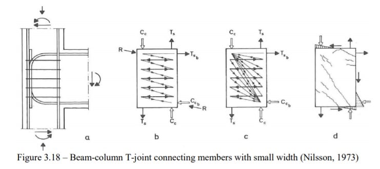
i found some doods masters thesis
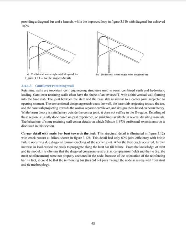
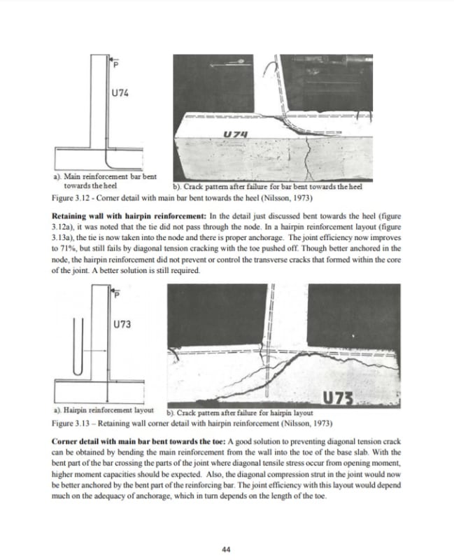
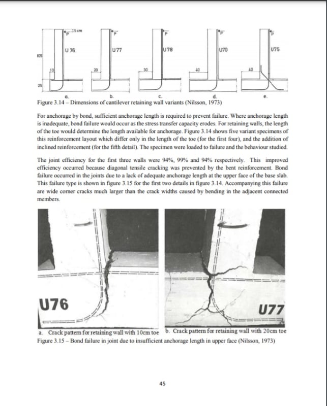
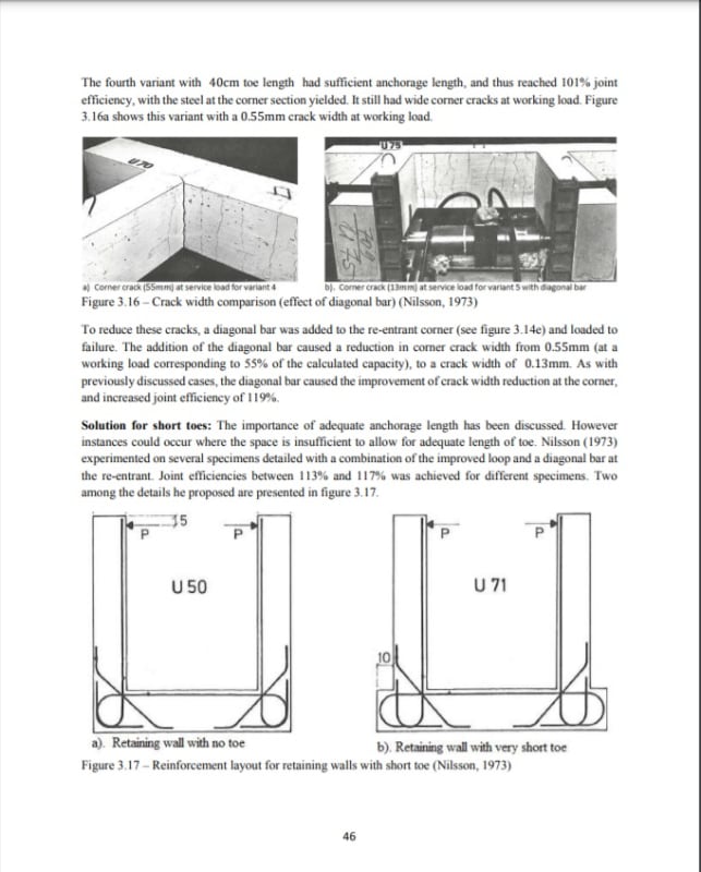
he quotes alot of nilsson stuff for people who dont have access to his material

also strut and tie model to analyze retaining walls

 
wrxsti said:
i found some doods masters thesis
Really great stuff here. Thanks for sharing. From everything that's been said here and on other threads it sounds like those 'D' bars are really important in getting full moment capacity out of the joint but most engineers aren't putting them in on smaller scale projects. In that thesis he makes it sound like having top bars in the slab is a good alternative for putting in the diagonal bars.
 
i dont think it is a requirement but you may not be able to get sufficient anchorage on
prescribed development lengths or geometry limitations (like your case)
NOTE: anchorage cannot be achieved by bending into the heel as your tie needs to be anchored into the node

the guy describes this when his FEM results have better performance than Nilssons experimental results

i think the takeaway though was your detailing of bending towards the heel

which D bars will not help the diagonal tension failure here (SEE FIG 3.13 where sufficient anchorage was provided)

see his quote "The use of looped reinforcement arrangement of the main tension reinforcement properly done gave the
best result. Adding a diagonal bar at the re-entrant corner improved the result even further for looped details.
However, the use of diagonal bar does not help significantly for details susceptible to diagonal tension
cracking
. However, where stirrups were used for such details, and placed in a fan-shaped arrangement (i.e.
smearing outwards from the inner corner to the outer, thus crossing the crack trajectory) improvement were
made and the joint thus reached full capacity. This is however contrary to the result Nilsson (1973) obtained
with stirrups, as the stirrups gave marginal benefit in that case, without reaching 100% efficiency. More
experiments from other authors could clarify this discrepancy.
On the impact of increasing joint size for a corner joint susceptible to failure by diagonal tension failure,
three sample of different size with comparable reinforcement ratio (for the tradition layout in figure 3.3a).
The specimen sizes were 150 × 250 𝑚𝑚2 , 150 × 350 𝑚𝑚2 and 150 × 450 𝑚𝑚2. Thus, with each
increase in specimen thickness, the lever arm increased. As expected, the failure load increased with
50 increasing specimen thickness, thus the section could carry more. However, the joint efficiency reduced
with increasing thickness, as the sections still failed by diagonal tension. Diagonal tension failure depends
on the tensile strength of the concrete (where stirrups or crossing reinforcement is not provided), and thus
increasing section thickness only increases the length of the crack path, but not concrete tensile strength.
"

the guys STP model shows how to calculate the transverse tensile force. (im not a STP expert though to confirm the accuracy)

see his quote "Thus, a tension force of 145.4𝑘𝑁 is estimated from the transverse tensile stresses within the joint. Even if cracking is not prevented, the structural detail of the wall-base connection should be capable of preventing diagonal tension cracking failure from these tensile stresses. Typical strategies used for this purpose includes bending the main reinforcement into a loop within the joint, use of inclined stirrups to control the cracks, use of bent bar to cross the strut path etc. This topic was discussed extensively in section 3.4 of this report"


the guy goes on to talk about detailing ties transverse (or inclined stirrups) to this strut to accomodate the diagonal tension

i have not seen any details like this for retaining walls (if anyone would be much obliged)
maybe just traditional vertical ties and stirrups to confine the strut?

engtips1_rf3sab.jpg


but
as suitable quoted since not seen in many cantilever walls
"In concluding this section of the report, it should be noted that Nilsson (1973) regarded the use of stirrups
in corner joints as difficult to construct on site. It could also lead to congestion of the joint which may result
in difficulties during pouring and compacting of concrete. Unlike Nilsson however, several other
researchers recommend the use of stirrups within the corner joint to control diagonal tension crack failure.
"


it seems like the economical solution is to loop the stem steel or hairpin with additional bars SEE FIG 3.17 in my post above
or turn the bend in the direction of the toe (SEE FIG 3.14) <--- this method could suffer from insufficient anchorage hence D bars
 
 
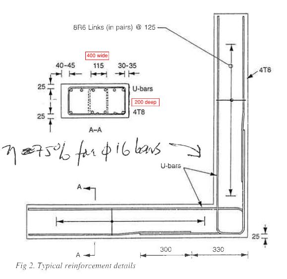
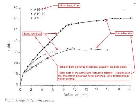
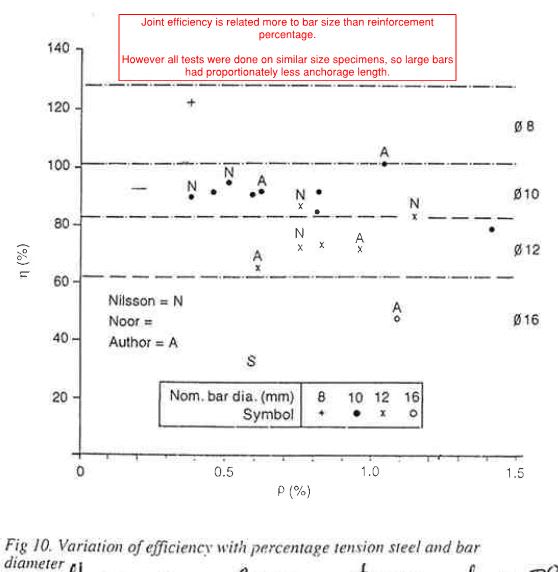
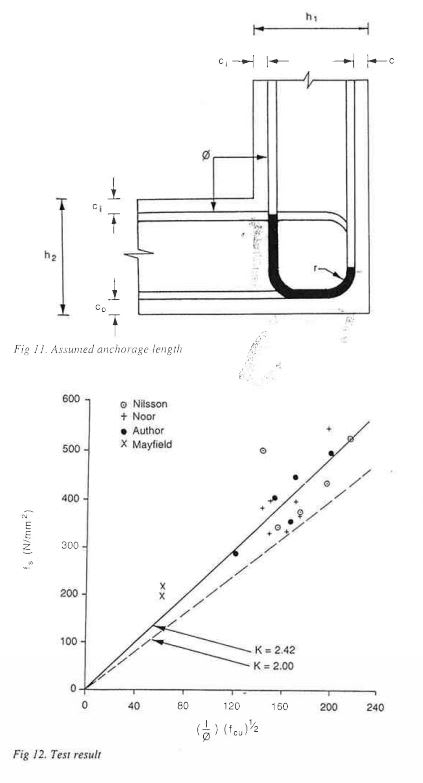
Because Nilsson's tests have been brought up, and the initial design was an 8" stem matching the ~200mm used in lab tests, I'll give a pointer to the following interesting articles on opening corners by N. Jackson (possibly Neil Jackson). Jackson revisited Nilsson's tests and those of another researcher (Noor), supplemented with his own tests. Only overlapping U-bars are considered as that was the ACI recommended detail at the time, but there should be some relevance beyond this. U-bars would be my recommendation for the wall under discussion here.

Jackson's hypothesis is that the ratio of available bond length within the corner to the bar size determines whether full strength and ductility are achieved in the opening corner joint - similar to the usual calculation of bar development. The images below are from the first article (without diagonal reinforcement), with my summary in red. Note that researchers tend to use smaller bars than real structures so Nilsson's raw results would be optimistic for 5/8" bars.

Jackson_Fig2_awunse.jpg


Jackson_Fig3_kupl6a.jpg


Jackson_Fig10_xuqp4k.jpg


Jackson_Fig11_12_wpynje.jpg


The diagonal bar article gives recommendations on diagonal quantity for a given crack width at service loads. As a bonus, the diagonals increase the section capacity within the joint because they pass through the tensile zone at the critical section, which reduces the stress in the main U-bars, but this is not considered in the ultimate design.

Corners without diagonal bars:


Corners with diagonal bars:
 
Status
Not open for further replies.

Part and Inventory Search

Sponsor