Continue to Site

Eng-Tips is the largest engineering community on the Internet

Intelligent Work Forums for Engineering Professionals

  • Congratulations KootK on being selected by the Eng-Tips community for having the most helpful posts in the forums last week. Way to Go!

12m canopy steel beam to rc concrete connection

Status
Not open for further replies.

istruct1980

Structural
Jun 29, 2019
19
hello am i missing something?

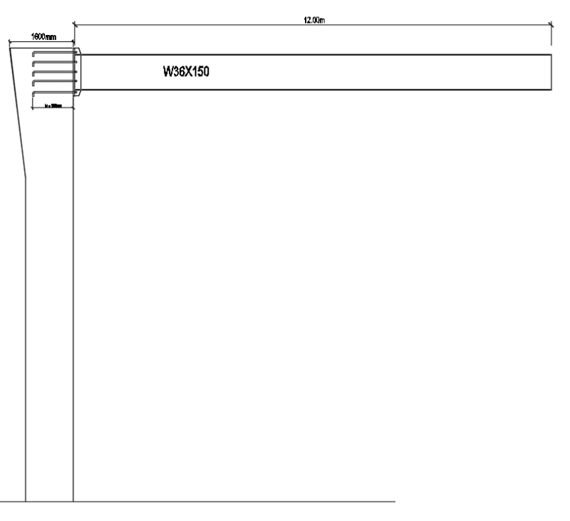
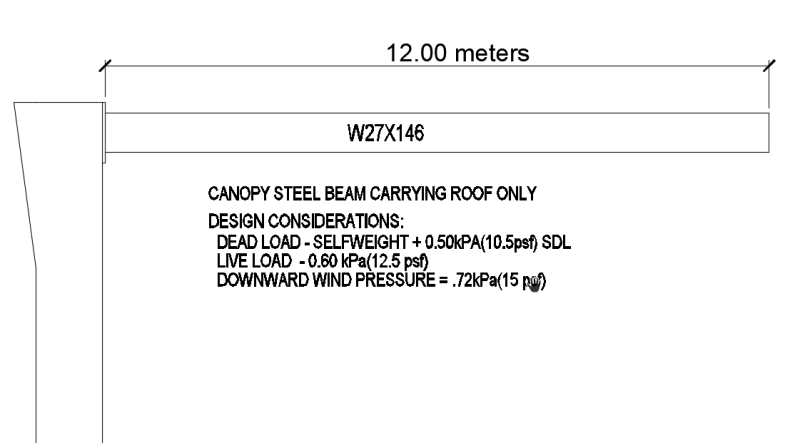
the steel canopy is 12m long with a spacing of 6m(column to column distance)

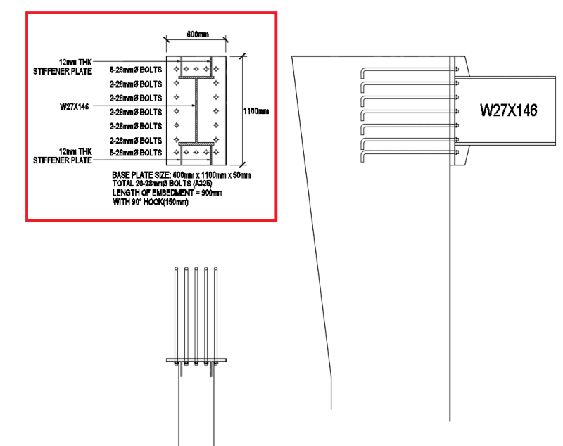
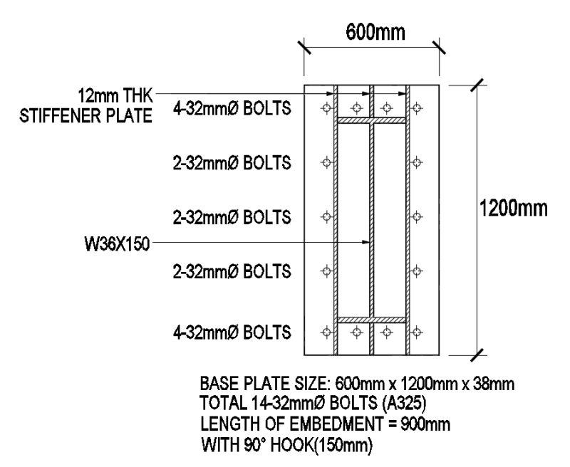
loadings shown in the image, and i got these design results:

1_ntnsub.png


2_hlur97.png


3_r1uxrz.png


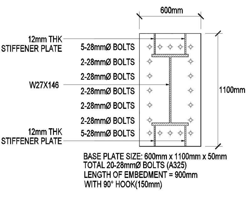
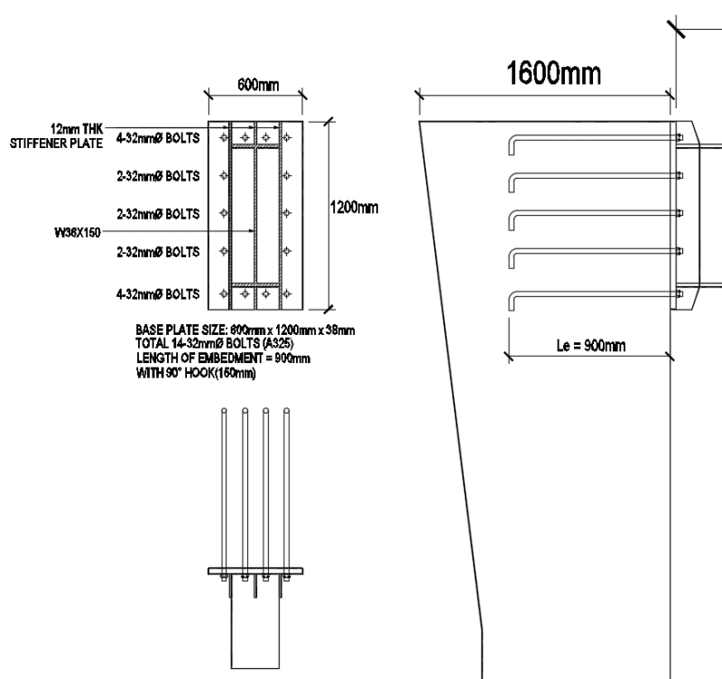
in my computation for bolts required due to resisting moment is only 5 bolts on the outermost layer,
what would be the maximum spacing for each bolts?
i just put 2 in each such that it wont be spaced 150mm farther apart.
 
Replies continue below

Recommended for you

I think you have carried through the steel portion of the design. More importantly, however, will be the reinforced concrete aspects of this structure. The bolt spacing will be based upon the required concrete connection requirments, I anticipate that concrete break-out will control based upon what you have shown. Graphically, the cantilever column appears to be rather skinny in consideration to the magnitude of the moment it will be carrying. Close consideration of its capacity, deflection and connections - considering any P-delta effects - are warranted.

As a separate note, your roof live loads would be small in my municipality (20psf min.)
 
EZBuilding has a lot of good points about the concrete column. Another one...the primary tension bolts are too close to the top of the column.
 
Also consider what's occurring in the concrete beam-column joint to resolve the temsion/compression couple. You're going to need some joint reinforcement, can you even fit it in for example.

I don't really like the steel arrangement that much for the following reasons

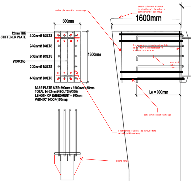
I think your 12mm stiffeners aren't really that effective as they just want to bend the flange as they are not very deep. Usually they are central on the web in typical connections of this type so they are actually effective due to the continuity with the Web. Additionally the aspect ratio looks wrong, do they even work for combined shear and bending for example? Usually they might be 2-3 times longer than they are deep. You'd also typically see the bolts distributed evenly above & below the flanges, rather than the 'box' arrangement you show with bolts only around the perimeter resulting in bolts on one side of the falnges. The arrangement you show allows the flange to more easily pry off the concrete surface leading to additional deflections in the cantilever. The bolts on the sides probably are not doing what you assume given the distance to the web. Usually you try get the bolts to all be a similar distance from the flanges top and bottom of flanges, as detailed some bolts will see more load than others and estimating this effect is difficult as its stiffness driven. Better to keep things symmetrically placed so you can better estimate the forces and get an even distribution of force out of the flanges. You shouldn't bend bolts like shown, you'll just end up with a high potential of cracking the threads.

You didn't note how you designed it? Did you follow a recognised methodology? Does you code require that the brittle failure mechanism of the bolts failing in tension needs to not govern (for example plate fails first, I ask because your bolts seem very small vs the 50mm thick plate). I didn't bother working out any design actions from your loads though.
 
One more issue is the hooks on the bolts. That method has been shown to be not effective, thus is obsolete. Headed bolts are used now.
 
i think its okay?, just have to add more covering of the top tension bolts.
 
I don't think you have addressed some of the concerns/suggestions that were made with your latest design iteration and you have not responded to some of the questions that were made? I still don't know what loads this connection is subject to, nor do I know what capacity you think it has apart from stating you think it's okay? This doesn't sound like even you are convinced it's actually okay, and it's not really convincing me.

Overall it still looks wrong to me I'm afraid. For example you still have bolts on only one side of the flange, you still have these bent bolts providing the anchorage, you have the bolts virtually hard against the stiffeners (can they even be tightened?) (you'll just overload the weld locally, especially critical if it's intended to be a fillet weld), no information on welding is given at all (has it been reviewed/designed yet?), no depth/width of stiffeners is given (the full depth one looks suspect, does it work for the loads imposed from the bolts acting as a beam?), there is limited connection of full depth stiffener to the side of the flange (two fillet welds presumably to take a large proportion of the loads in probably 2-3 bolts), still have square layout of bolts which was mentioned as not being desirable, etc. How do you plan on ensuring the bolts are placed within tolerance within the concrete? Does the bearing on the concrete even work (under the compression flange)?

Edit - As people have noted, the concrete side of the connection will no doubt limit the connections capacity, and nothing has been provided in this regard.

This is more what I was thinking if I was presented with the same problem (of course I have no idea what the loads actually are), maybe other agree/disagree in terms of it being a more standard simplified/well experienced/tested approach? I'd design the end plate to the requirements of SCI398 as thats pretty much the state of the art method for this type of thing.
 
I'd add as well, you might get more benefit on the concrete side of the connection with a tapered member that was deeper at the support and thinner at the tip in terms of lessening the localised forces on the concrete for bearing and beam-column joint design. Additionally architect might appreciate this aspect.

If the concrete didn't work, then I'd suggest the possibility of looking at concrete encasing a steel member to form a composite steel/concrete column and making the moment connection in steel which is potentially easier to deal with larger forces.
 
Agent666 said:
I'd suggest the possibility of looking at concrete encasing a steel member to form a composite steel/concrete column and making the moment connection in steel which is potentially easier to deal with larger forces.

I'd been thinking along these lines for a different reason. Given the nature of the structure that you've got here, I would have some concern for the fatigue performance of the connection. And, particularly on the concrete side, that's not an easy thing to evaluate. I feel that a steel to steel connection on an embedded shape would alleviate much of this.

HELP! I'd like your help with a thread that I was forced to move to the business issues section where it will surely be seen by next to nobody that matters to me:
 
Status
Not open for further replies.

Part and Inventory Search

Sponsor