Continue to Site

Eng-Tips is the largest engineering community on the Internet

Intelligent Work Forums for Engineering Professionals

  • Congratulations waross on being selected by the Eng-Tips community for having the most helpful posts in the forums last week. Way to Go!

1940s Steel Double Warren Truss

Status
Not open for further replies.

Guastavino

Structural
Jan 29, 2014
381
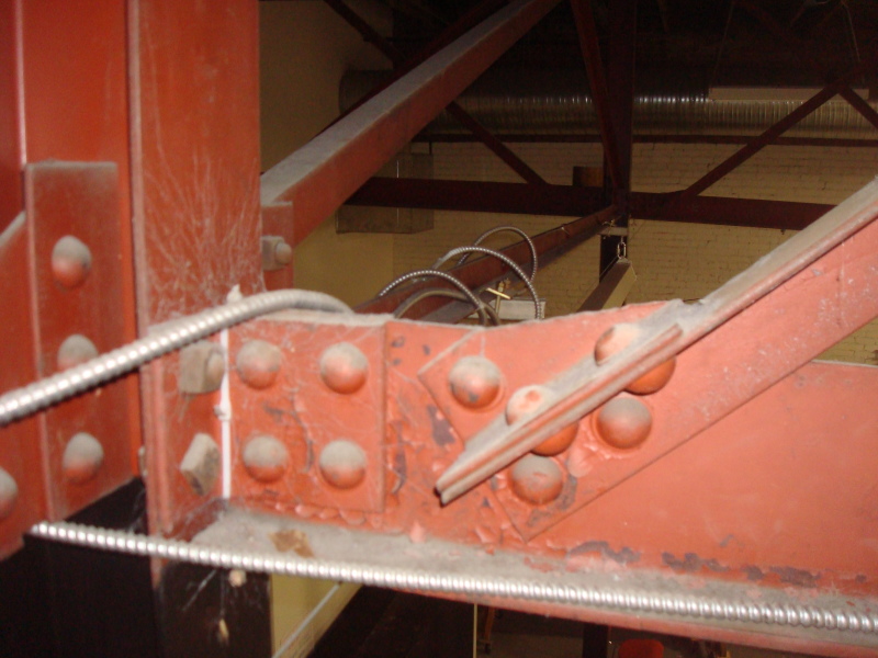
Interesting Fun problem here. So I have a what I think is a double warren truss (ISH). It spans about 50' and you are seeing the mid-span in the picture. So they are single angles that are riveted at the midpoint.

It appears as though the original designer assumed that the rivet point at the center was a brace point. Frankly, I don't disagree because the opposite side angle is in tension when one is in compression (Generally speaking).

So It also appears that the original designer did not assume eccentricity for single angle compression, because well, he likely didn't have a computer back in 1940. SO, with that said, I'm tasked to determine load capacity of the roof. Frankly, I don't have too many issues with assuming concentric load and a brace point at the center. Each angle has double rivets on the end, so it's more or less "fixed" to the WT top and bottom chords. Also, that RIVET at the center really does stiffen the whole thing up a lot, because in order to buckle, it would have to buckle a high tensioned angle. I don't see that happening.

I'm not trying to get ridiculous load capacity out of the truss. It should have been designed for 30 psf per the 1936 building code. I only want 20 psf of live that I can then reduce to the local snow load to tell them they can hang say 5-8 psf. The roof wood members are rated for right about 30 psf. So I'm thinking that the truss was "designed" for around 20-30 psf of live load. If I use eccentric loading the truss wont work. So what I'm really asking is, am I stepping too far out on a limb here?
 
 http://files.engineering.com/getfile.aspx?folder=7076b0f7-14bb-4b2d-8d13-cd677c4baf54&file=Capture.JPG
Replies continue below

Recommended for you

For built up laced members (on a smaller scale, but I think the concept is the same), we typically take the unbraced length of the compression lace to be 0.7*L (total length from chord to chord) and assume buckling about the geometric axis. This is to account for the partial restraint provided by the connection to the tension lace.

We also typically neglect eccentric loading, but I don't know if that's technically correct or not.
 
Are there only two vertical members in the truss shown by yellow vertical lines?

Members do not meet at a point at the supports. Chords should be checked for bending.

I suspect that the engineer considered the diagonals braced at midpoint in the 1940's but I don't believe it is a valid assumption according to the practice of today. 0.7L seems a more prudent figure for the unbraced length of the compression diagonals.

Eccentricity of load should be considered because it is there, albeit fairly small.


BA
 
You are correct, there are only (2) truss verticals. An odd shaped truss no doubt.

What about using the "bracing" nodal equations and considering the stiffness of an angle on the opposite side that is in tension? And see if that works.

I don't think The 0.7L will get the truss there. I'm ok with that if that is what it needs to be, but I'd like to fight to make it work for my clients sake if I can. (color me KootK for trying the impossible for the sake of a client) If it doesn't, it is what it is. I don't know of any codified approach to such an odd Conditon, so I want a reasonable approach, whether the results end up good or bad. 0.7L seems conservative but maybe more so than needed.

As for eccentricity, honesty I'm not even sure how to apply that with accuracy. I don't see it contributing significantly, in that it's short spans with minor moments and nearly fixed end Conditons. I agree it should be accounted for, but I'm not sure of an approach that will actually capture it with any realistic accuracy. Any thoughts?
 
The appropriate K value for X bracing connected at midspan has been beat to death here. As for eccentricity, in the Canadian code there is a clause for calculating compressive resistance of angles neglecting eccentricity. I'm sure there is an equivalent clause in the AISC spec, but I don't have my copy with me.

Here is some reading on the effective lengths

"Design of Diagonal Cross Bracings" Part 1, 2, and Discussion. Picard and Beaulieu. Engineering Journal, AISC 3Q 1987, 4Q 1987, and 4Q 1989,

"Effective Length Factor for the Design of X-bracing Systems" El-Tayem and Goel. Engineering Journal, AISC 1Q 1986
 
Right, AISC E5 allows eccentricity to be neglected if a modified KL/r is used (and some other criteria are met).
 
Nick said:
What about using the "bracing" nodal equations and considering the stiffness of an angle on the opposite side that is in tension? And see if that works.

This is exactly what I would do. I bet your proportions are a bit stockier than your average double angle braced frame etc.

Nick said:
each angle has double rivets on the end, so it's more or less "fixed" to the WT top and bottom chords.

I'd be careful with this. Because the angles alternate sides along the chords, they induce a torsion in those chords that, in my opinion, is resisted by the bending stiffness of the webs. I think that means that the webs being moment connected to the chords results in more bending in the webs, not less.

Nick said:
I agree it should be accounted for, but I'm not sure of an approach that will actually capture it with any realistic accuracy. Any thoughts?

It's a ton of work but tractable. How about:

- Assume pins where webs are connected to chords.
- Do the AISC nodal bracing thing.
- Mf = axial x e + 1/2 torque delivered chords at each panel point.
- Dive deep into the code and check buckling & section capacity about geometric strong axis, geometric weak axis, principal axis, torsional axis. It would be nice if you had a spreadsheet.

If you have the resources available, two places to look for historically justifiable simplifications might be:

1) The transmission tower codes. I believe that's the usual source on the 0.7.
2) The standards that govern OWSJ design

Another concern that I have for your truss is that there appears to be a lot continuity across the column on the left end. That makes me fear for the viability of your bottom chord.

How about a load test? It'll work out and you've got easy access here and only a few isolated things to test so it ought not be too onerous. I find that clients often react favorably to load tests when they don't cost a fortune. It's something that they can "feel" on an intuitive level. Plus it creates the impression that you're a bold, practical fellow willing to go the mat to squeeze every last nickel of value out of your clients' structures. Write a Structuremage article, post it on your website, beat new clients of with sticks...

I like to debate structural engineering theory -- a lot. If I challenge you on something, know that I'm doing so because I respect your opinion enough to either change it or adopt it.
 
All interesting posts here, thanks. So one other thought is that the back side angle is always in tension when the worst case angle is in compression. So the worst case axial load in the angle is around 16k. This requires a nodal bracing force=0.01*16000=160#. If my back side angle can resist that in bending for it's 8' length and is stiff enough using the PL^3/48EI equation with a unit load at the center (including stiffness added from the axial tension), I think I have a solid argument to assume a nodal brace point. Any structural heresy in that? I really think that an angle in significant tension will NOT want to move, and if I can figure a way to calculate how "stiff" that is, and if it's stiff enough to qualify based on Betabr=Omega*8*Pr/Lb, I think I've got something to stand on.

Also, the worst case angle they connected both legs of the angle to the bottom chord. So, I don't think concentric loading is as difficult to reason.

KootK, what is the "1/2 torque delivered chords at each panel point."?
 
Nick said:
If my back side angle can resist that in bending for it's 8' length and is stiff enough using the PL^3/48EI equation with a unit load at the center (including stiffness added from the axial tension), I think I have a solid argument to assume a nodal brace point.

Mostly agree. I'd leave the tension stiffness out of it for calculation purposes.

Nick said:
Also, the worst case angle they connected both legs of the angle to the bottom chord. So, I don't think concentric loading is as difficult to reason.

I actually think that this is worse than the typical condition:

1) Your line of force is further from the centroid of the section (equal legs assumed).
2) You've now got weak principal axis buckling (probably the worst one) oriented in the direction that offers the least amount of lateral/end rotation restraint.

Nick said:
KootK, what is the "1/2 torque delivered chords at each panel point."?

Imagine your chord in section with up and down axial loads delivered either side of the tee stem representing the vertical component of the axial forces being delivered by the webs. It's not huge, but it's real.

I like to debate structural engineering theory -- a lot. If I challenge you on something, know that I'm doing so because I respect your opinion enough to either change it or adopt it.
 
CanwestENG,

So that article "Effective length factor..." you mentioned is fantastic (Thank you). And, it states the following conclusions:

1. Design of X-bracing systems should be based on exclusive consideration of one half diagonal only.
2. For x-bracing systems made frome single equal-leg angles, an effective length of 0.85 times the half diagonal length is reasonable.
3. The proposed theoretical model can be used for estimating the effective length factor in any direction and for any cross-sectional shapes.

Now color me happy if I'm interpreting that correctly....I just can't believe it to be true. That would be too good...granted that article is for braced frames and a truss isn't that, but the point is it seems like I could use K=1.0 and the Half-length to calculate my allowable load on my angles and be OK.

Anyone read those conclusions and think my interpretation is way off?

And KootK, the angle in question is L3x2.5x1/4 (8' long on the diagonal, 4' on the "half diagonal"). Eccentrically loaded per current tables roughly gets you 7.88 kips. Concentrically loaded gets you 18 kips. Both assuming a 4' unbraced length. Below is the actual connection. That difference is clearly huge and makes the difference in working and not working. I'm gonna have to ponder on this!

160019-PHT_2016-06-09_023_fa6gv7.jpg
 
Also, as I continue to study, the Old references I have only publish values for concentric angle loading, which conveniently works out to be the design loads (roughly). I'm beginning to believe the original designer used L/2 for the effective length and a concentric load assumption. The L/2 seems reasonable, but the more I look into this, the more I think the concentric assumption isn't OK. I think I'm gonna have to tell the folks, no dice, you can't hang stuff from it.
 
Nick said:
That difference is clearly huge and makes the difference in working and not working. I'm gonna have to ponder on this![/quote

The webs connecting up close to the column (pic above) could be considered fairly well restrained I would think. Tee sections have crap torsional stiffness but even that ought to be sufficient 8" from the column.

I like to debate structural engineering theory -- a lot. If I challenge you on something, know that I'm doing so because I respect your opinion enough to either change it or adopt it.
 
Oh, and I love the real life Whitmore section on the connection.

I like to debate structural engineering theory -- a lot. If I challenge you on something, know that I'm doing so because I respect your opinion enough to either change it or adopt it.
 
Problem is that the other end is the same but 7' from the column or so. I think this is Ph.D. Type of a study here haha. I just don't think I can justify concentric loading to make it all work. Clearly it's a complex situation, but I certainly don't have the fee in it to do that complex a calculation (in other words, that complexity goes beyond me).

Point is, to make it all seem to work i would need almost pure compression concentrically, which I don't have but you could likely get closer with a fancy analysis.

Thinking out loud here...
 
Status
Not open for further replies.

Part and Inventory Search

Sponsor