TopPocket
Mechanical
- Feb 16, 2022
- 50
Hia,
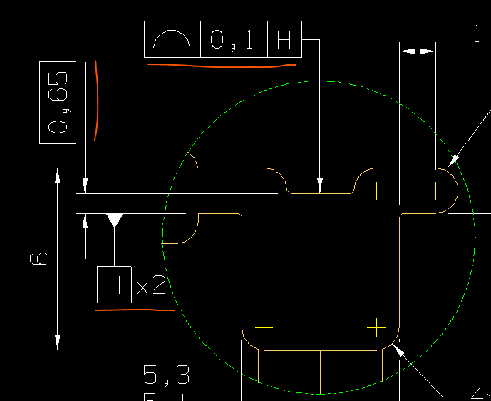
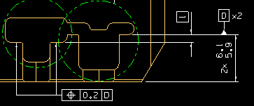
So I wish to define an irregular feature of size - the 0.6/0.7 dimension in the pocket:
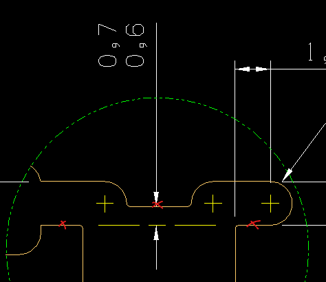
So I want to measure a line between the two aligned faces and then measure the distance to a point on the top face. I feel doing a x2 0.7/0.6 would suggest I want 2 measurements from each of the aligned faces to the top face which would mean constructing a tiny line on each face. but this isn't really the design intent. How do I imply a link between the two aligned faces?
Now I've put a centerline to connect the two side faces to try help explain what I want to do. Essentially I'm looking to probe the 3 points "x" and calculate the specified dimension.
I thought maybe you could define a datum between the 2 aligned faces (but then how is that done when there is a gap? - a bit of a tangent) and spec the top face to the datum. To be clear the pocket isn't very deep, but you could probably get a plane if you wanted.
Thoughts?
(to BS8888)
So I wish to define an irregular feature of size - the 0.6/0.7 dimension in the pocket:
So I want to measure a line between the two aligned faces and then measure the distance to a point on the top face. I feel doing a x2 0.7/0.6 would suggest I want 2 measurements from each of the aligned faces to the top face which would mean constructing a tiny line on each face. but this isn't really the design intent. How do I imply a link between the two aligned faces?
Now I've put a centerline to connect the two side faces to try help explain what I want to do. Essentially I'm looking to probe the 3 points "x" and calculate the specified dimension.
I thought maybe you could define a datum between the 2 aligned faces (but then how is that done when there is a gap? - a bit of a tangent) and spec the top face to the datum. To be clear the pocket isn't very deep, but you could probably get a plane if you wanted.
Thoughts?
(to BS8888)